
User`s guide

0
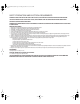
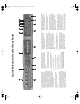
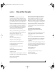
Quick Reference: Traveler Front Panel
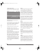
1. These four detented digital trim knobs provide 53dB of
gain, but they also function as pad switches (when
pushed) for an additional 20dB of gain or reduction.
When you turn or push the knobs, you’ll see dynamic
feedback of your adjustment in the LCD display. The total
gain range — from when pad is enabled and the trim is
turned all the way down to when the pad disabled and
trim is turned all the way up — is 73dB. All four inputs
have preamps, so you can plug in just about anything: a
microphone, a guitar, a synth, or even a +4 signal. Use
the trim knob and input level meters 1-4 in the metering
section to calibrate the input signal level. The meters
cover both the TRS and XLR input.
2. Controls the headphone volume or main out volume.
Push to toggle between them. The LCD provides
feedback.
3. This section controls the Traveler’s built-in CueMix DSP
monitor mixer. There are four independent mix busses:
MIX1 through MIX4. Each mixes all inputs (or any subset
you wish) to a stereo output of your choice. To edit a mix,
choose it by pressing the MIX BUS knob. Each mix has
parameters (volume, pan, etc.) for each input: choose
the parameter you wish to edit with the PARAM knob.
The LCD shows each Traveler input (XLR/combo, TRS,
ADAT, SPDIF and AES/EBU), along with the current mix
parameter setting for each input. To change a setting,
scroll to it with the CURSOR knob and change it with the
VALUE knob.
4. These four 4-segment meters show input signal level for
the mic/instrument XLR/combo inputs on the rear panel.
5. These four 4-segment meters show input signal level for
the analog TRS input jacks on the rear panel.
6. 4-segment metering for S/PDIF input.
7. MIDI activity LEDs for MIDI input and output.
8. 4-segment metering for AES/EBU input.
9. ADAT optical and TOSLink signal present LEDs.
10. When the Traveler is resolving to SMPTE time code, the
LOCK light glows green when lockup has been achieved.
The TACH light blinks once per second when the Traveler
is successfully reading address (time code) information.
11. The Traveler is powered by its FireWire connection to the
computer. Use this power switch to turn it on and off. It is
recommended that you always power off the Traveler
before unplugging the FireWire cable.
12. These lights indicate the global sample rate at which the
Trav el er is operating. Use the MOTU FireWire Audio
Console to set the sample rate or to choose an external
clock source, from which the sample rate will be derived.
When no clock signal is currently present, one of these
LEDs flashes rapidly. For example, if you’ve set the
Trav el er to slave to an external clock, such as ADAT, but
there is no clock signal currently being detected, it
flashes.
13. These four round “L/R” LEDs indicate signal presence on
the stereo S/PDIF and AES/EBU digital outputs.
14. These round LEDs indicate signal presence on the eight
rear-panel TRS analog outputs. Their threshold is around
-42 dB. They do not indicate clipping in any way; use your
host audio software level meters to calibrate output
levels. Outputs 1-2 serve as the main outs. Push and
then turn the front-panel volume knob for volume
control.
15. The multi-purpose backlit LCD shows system settings or
CueMix DSP settings, depending on which knobs you
turn. The labels above and below the LCD refer to all of
the Traveler’s inputs (both analog and digital).
16. Use the VALUE and CURSOR knobs to adjust the CueMix
settings (gain, pan, etc.) for individual inputs.
17. Use the SETUP and SELECT knobs to change system
settings like the Traveler sample rate and clock source.
The SETUP knob chooses the setting; the SELECT knob
modifies the current system setting displayed in the LCD.
Some settings require that you push SELECT instead of
turning it, or you may need to push it to confirm the
setting you’ve chosen by turning it.
18. This is a standard quarter-inch stereo headphone jack.
From the factory, its output matches the main outs on
the rear panel. But it can be programmed to mirror any
other output pair (digital or analog). It can even be
programmed to serve as its own independent output.
Use the volume knob above to control its level.
19. These switches provide phantom power for their respec-
tive microphone input. Left is off; right is on. (Right on!)
1 2 3 4 5 6 7 8 9 10
111213141516171819
!Traveler Manual/Win Page 5 Monday, November 29, 2004 3:50 PM