
User`s guide

INSTALLING THE TRAVELER HARDWARE
22
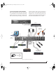
shown in Figure 4-3. Similarly, devices that never
send data, such as a sound module, only need
Connection A. Make both connections for any
device that needs to both send and receive MIDI
data.
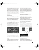
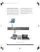
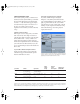
Connecting additional gear with MIDI THRUs
If you need to connect several pieces of MIDI gear,
run a MIDI cable from the MIDI THRU of a device
already connected to the Traveler to the MIDI IN
on the additional device as shown below in
Figure 4-4. The two devices then share the
Traveler’s M I DI OUT port. This means that they
share the same set of 16 MIDI channels, too, so try
to do this with devices that receive on only one
MIDI channel (such as effects modules) so their
receive channels don’t conflict with one another.
Figure 4-4: Connecting additional devices with MIDI THRU ports.
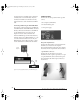
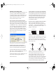
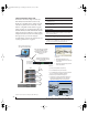
POWER OPTIONS
The Traveler can draw power from three possible
sources:
1. the computer (via FireWire)
2. an external battery pack
3. a DC power supply
Figure 4-5: The Traveler’s battery and power supply options.
Bus power requirements
The Traveler draws all the power it needs from the
FireWire bus connection to the computer.
However, the FireWire connection to the computer
must meet all of the requirements discussed below.
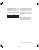
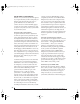
6-pin FireWire connectors
The Traveler can only draw power over the
FireWire bus from a 6-pin to 6-pin cable, or a 6-pin
to 9-pin (FireWire B) cable. It cannot draw power
from a FireWire cable with a 4-pin connector, as
shown below:
Figure 4-6: 4-pin FireWire connectors cannot be used for bus power.
MIDI IN
MIDI
cable
MIDI Device
MIDI
IN
MIDI
THRU
MIDI
OUT
Additional device
Trav eler
side panel
6-pin FireWire
4-pin FireWire
✓
✗
YES
NO
!Traveler Manual/Win Page 22 Monday, November 29, 2004 3:50 PM