
User`s guide

INSTALLING THE TRAVELER HARDWARE
21
To t o g g l e t h e p a d , push the input’s trim knob. The
LCD provides feedback for the current pad setting.
The pad settings above are recommended initial
settings. Use the front-panel trim knobs to adjust
input levels, and use the Traveler’s front-panel
4-segment meters to adjust the gain accordingly. If
necessary, after adjusting the trim, you can enable
or disable the pad as needed, depending on actual
signal levels.
Quarter-inch analog
The quarter-inch analog inputs (5-8) and outputs
(1-8) are balanced TRS connectors that can also
accept an unbalanced plug. The outputs are all
referenced to +4dBu. The inputs can be manually
set to either +4 or -10dBu. Use the front panel
controls to adjust the reference level (+4/-10) as
needed for each input (or input pair) as follows:
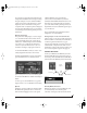
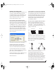
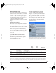
1 Tur n the PAR AM k n o b u ntil you see the “4/10”
setting displayed in the LCD, as shown below.
If turning the PARAM knob doesn’t do anything,
press the SETUP knob once, and then turn it.
Figure 4-2: Setting the reference level for the four TRS analog inputs.
2 Tur n t he CURSOR knob until the desired input
flashes.
3 Tur n ( or press) the VALUE knob to toggle the
input between a +4 or -10dB reference level setting.
Optical
Reminder: optical goes OUT to IN and IN to OUT,
like MIDI. The optical jacks can be connected to
either an ADAT “lightpipe” device or an optical
S/PDIF “TOSLink” device. Just make the
connections as needed and then you’ll set the
format later in the MOTU FireWire Audio Console.
Input and output are independent. For example,
you could connect ADAT optical input from your
digital mixer and connect TOSLink optical output
to your DAT deck.
The optical S/PDIF jacks are disabled at the 4x
sample rates (176.4 and 192kHz).
Analog outputs 1-2 can serve as main outs
Analog outputs 1-2 can serve as main outputs. The
main out volume is controlled by the volume knob
on the front panel. Push the knob to toggle
between phone and main out volume control. In a
standard studio configuration, the main outs are
intended for a pair of studio monitors, but they can
also be used as regular outputs for any purpose.
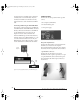
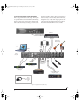
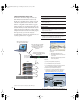
CONNECT MIDI GEAR
Connect your MIDI device’s MIDI IN jack to the
Traveler’s M I DI OUT jack (Connection A below).
Conversely, connect the MIDI device’s MIDI OUT
jack to the Traveler’s MIDI IN jack (Connection B).
Figure 4-3: Connecting a MIDI device to the Traveler.
One-way MIDI connections
MIDI devices that do not receive MIDI data, such
as a dedicated keyboard controller, guitar
controller, or drum pad, only need Connection B
Trav eler
rear panel
MIDI Device
MIDI
cables
MIDI
IN
MIDI
OUT
MIDI
OUT
MIDI
IN
Connection A
Connection B
!Traveler Manual/Win Page 21 Monday, November 29, 2004 3:50 PM