OCDWB01 OPERATOR CONTROLLED DISCHARGE FOR WALK-BEHIND UNITS Part No. 4500-569 Rev.
Exmark reserves the right to make changes or add improvements to its products at any time without incurring any obligation to make such changes to products manufactured previously. Exmark, or its distributors and dealers, accept no responsibility for variations which may be evident in the actual specifications of its products and the statements and descriptions contained in this publication. © 2010—Exmark Mfg. Co., Inc. Industrial Park Box 808 Beatrice, NE 68310 2 Contact us at www.Exmark.com.
Introduction CONGRATULATIONS on the purchase of your Exmark equipment. This product has been carefully designed and manufactured to give you a maximum amount of dependability and years of trouble-free operation. This manual contains operating, maintenance, adjustment, and safety instructions for your Exmark equipment. BEFORE OPERATING YOUR MOWER, CAREFULLY READ THIS MANUAL IN ITS ENTIRETY.
Contents Introduction ........................................................... 3 Safety ..................................................................... 5 Safety Alert Symbol ......................................... 5 Safe Operating Practices .................................. 5 Safety and Instructional Decals ....................... 7 Setup ...................................................................... 8 Assembling Discharge Deflector to OCDWB01 ............................................
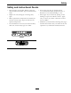
Safety Safety • Never let children or untrained people operate or service the equipment. Local regulations may restrict the age of the operator. Safety Alert Symbol • Only adults and mature teenagers should operate a mower, and even mature teenagers should have adult supervision. Be sure a teenager: This Safety Alert Symbol (Figure 1) is used both in this manual and on the machine to identify important safety messages which must be followed to avoid accidents 1.
Safety collection system or mulch kit in place and working properly. WARNING Removing standard original equipment parts, or using non-Exmark replacement parts and accessories may alter the warranty, traction, and safety of the machine. Failure to use original Exmark parts could cause serious injury or death. • Stop engine, wait for all moving parts to stop, remove key and engage parking brake: – Before checking, cleaning or working on the mower.
Safety Safety and Instructional Decals • Keep all safety signs legible. Remove all grease, dirt and debris from safety signs and instructional labels. • Replace all worn, damaged, or missing safety signs. • When replacement components are installed, be sure that current safety signs are affixed to the replaced components. • If an attachment or accessory has been installed, make sure current safety signs are visible.
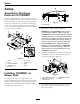
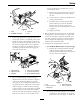
Setup Setup Assembling Discharge Deflector to OCDWB01 Insert the rod through the first tab on the gate link frame, discharge deflector, and second tab on the gate link frame (Figure 2). Orient and install the spring so that the loop will rest in the notch on the discharge deflector. Continue to push the rod into the linkage cover. Orient and install the hairpins into the ends of the rod as shown in Figure 2. Figure 3 1. Knock out tab 1. Flip up the existing discharge deflector.
Setup storage position for potential later use on other mower decks. A. Remove the shim located on the front of the gate link frame and loosely reinstall the nut. B. Loosen the nut on the left adjustment slot of the gate link frame. C. Install the shim between the gate link frame and the pivot mount assembly. Position the center tab of the shim between the two mounting bolts as shown in Figure 6. D. Tighten hardware. 4. Rotate the latch downward to lock the assembly in this position (reference Figure 5).
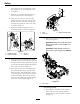
Setup there will be room to tighten the nut on the upper hole, on the underside of the front panel. C. Drill two 11/32 inch diameter holes on the front panel as shown in Figure 7. D. Align the two holes in the mounting bracket with the front panel of the unit. Install 5/16-18 x 5/8 inch carriage bolt through the upper hole and secure with 5/16 inch nyloc nut. E. Insert the handle assembly into the mounting bracket as shown in Figure 8. Figure 9 1. Knob 2. Loom clip 3. Handle assembly cable H.
Setup B. Align the existing hole at the rear of the unit with the right hole on the bracket. C. Position the bracket horizontally or with the narrow end pointed slightly downward. D. Using the mounting bracket as a template, mark the left hole location onto the side panel of the unit and drill 11/32 inch diameter hole (see Figure 11). Figure 12 1. Handle assembly 2. Mounting bracket 3. Clevis pin 4. Hairpin G.
Product Overview Product Overview Figure 14 1. Velcro strap 2. Loom clip Figure 15 1. Handle 2. Discharge gate (under discharge deflector) 3.
Operation Opening the Discharge Gate Operation For all Walk-Behind Units except Vantage: Rotate the handle upward to open the gate. Use the discharge gate to temporarily stop or deflect grass clippings away from sidewalks, parking lots, patios, or anywhere grass clippings are not desired to be discharged. The handle allows the discharge gate to be held in any position from fully closed to fully open. Important: Make sure the mower is in neutral before operating the handle of the discharge gate.
Operation Closing the Discharge Gate Removing the OCDWB01 For all Walk-Behind Units except Vantage: Push down on the handle to close the gate. 1. Remove and retain the velcro straps that secure the handle assembly cable to the mower. If installed, remove and retain the loom clip from the deck and replace the rear knob. 2. Remove the hairpin and clevis pin from the handle assembly. 3.
Operation Figure 21 1. Handle assembly 2. Mounting bracket 3. Clevis pin 4. Hairpin 4. Unlock the assembly and pivot it away from the mower deck. Lift the OCDWB01 out of the deck mounting tube. 5. Lower the existing discharge deflector. Important: Reinstall the original discharge deflector if it was removed during the OCDWB01 installation. 6. The machine can now be used for side discharge mowing.
Maintenance Maintenance Note: Determine the left and right sides of the machine from the normal operating position. WARNING While maintenance or adjustments are being made, someone could start the engine. Accidental starting of the engine could seriously injure you or other bystanders. Remove the key from the ignition switch, engage parking brake, and pull the wire(s) off the spark plug(s) before you do any maintenance. Also push the wire(s) aside so it does not accidentally contact the spark plug(s).
Maintenance 4 3 1 2 G012592 7 6 Figure 22 5 1. Pivot bolt and nut Figure 23 1. 2. 3. 4. 5. 6. 7. Discharge Gate Adjustment The discharge gate is properly adjusted in the closed position when the discharge gate is flat against the discharge opening. If the discharge gate does not close flat follow the steps below: Cable nuts Linkage cover (shown hidden for clarity) Lock nut Pivot adjuster Discharge deflector Gate pivot Cotter pin 5.
Troubleshooting Troubleshooting Important: It is essential that all operator safety mechanisms be connected and in proper operating condition prior to mower use. The following table lists some of the common causes of trouble. If assistance is needed, contact your Exmark Service Dealer. Problem Discharge gate does not open and/or close. Handle is too loose or tight. Possible Cause Corrective Action 1. Discharge gate is deformed. 1. Reshape the discharge gate. 2.
Exmark Commercial Attachments and Accessories 90 Day Limited Warranty Conditions and Products Covered Exmark Mfg. Co. Inc. and its affiliate, Exmark Warranty Company, pursuant to an agreement between them, jointly warrant on the terms and conditions herein, that we will repair, replace or adjust any part on these products and found by us (in the exercise of our reasonable discretion) to be defective in factory materials or workmanship for a period of 90 days.
SEE EXMARK’S COMPLETE LINE OF ACCESSORIES AND OPTIONS MID-MOUNT RIDING ACCESSORIES AND OPTIONS CUSTOM RIDE SEAT SUSPENSION SYSTEM OPERATOR CONTROLLED DISCHARGE FULL SUSPENSION SEAT ROLL OVER PROTECTION SYSTEM (ROPS) DECK LIFT ASSIST KIT SUN SHADE HITCH KIT TRASH CONTAINER LIGHT KIT TURF STRIPER 12V POWER PORT ULTRA VAC COLLECTION SYSTEM MICRO-MULCH SYSTEM ULTRA VAC QUICK DISPOSAL SYSTEM OUT-FRONT RIDING ACCESSORIES AND OPTIONS CUSTOM RIDE SEAT SUSPENSION SYSTEM SNOW BLADE DUAL-TAIL WHEEL SN