
User Manual

Maintenance
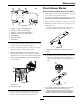
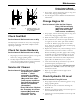
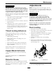
Figure19
1.Positive(+)cableondischargedbattery
2.Positive(+)cableonboosterbattery
3.Negative(–)cableontheboosterbattery
4.Negative(–)cableontheengineblock
5.Boosterbattery
6.Dischargedbattery
7.Engineblock
4.Connecttheotherendofthepositivecabletothe
positiveterminaloftheboosterbattery.
5.Connecttheblacknegative(–)cabletotheother
terminal(negative)oftheboosterbattery.
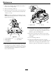
6.MAKETHEFINALCONNECTIONON
THEENGINEBLOCKOFTHESTALLED
VEHICLE(NOTTOTHENEGATIVEPOST)
AWAYFROMTHEBATTERY .STANDBACK
(see
Figure20).
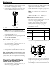
Figure20
1.Engineblock
2.Negative(–)cable
7.Startthevehicleandremovethecablesinthe
reverseorderofconnection(theengineblock
(black)connectionisthersttodisconnect).
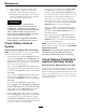
CheckMowerBlades
ServiceInterval:Beforeeachuseordaily
1.Stopengine,waitforallmovingpartstostop,and
removekey.Engageparkingbrake.
2.Liftdeckandsecureinraisedpositionasstatedin
theCleanGrassBuild-UpUnderDecksection.
3.Inspectbladesandsharpenorreplaceasrequired.
4.Reinstalltheblades(iftheywereremoved)inthe
followingorder:
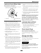
A.Installbushingthroughbladewithbushing
angeonbottom(grass)sideofblade.
Figure21
1.Installbushinginbladepriortoinstallingbushingin
spindle.
B.Installbushing/bladeassemblyintospindle.
Makesurethesplinesonthebushingare
engagedinthespindlebeforetighteningthe
bolt.
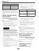
Figure22
1.Usewrenchhereforbladeinstallation.Thisnuthas
beentorquedto130–160ft-lb(176–217N-m)
2.Torqueto50-60ft-lb(68-81N-m)Applylubricantto
threadsasneededtopreventseizing.Copper-based
anti-seizepreferable.Greaseacceptablesubstitute.
33