
Mfg. Co. Inc. Lawn Mower User Manual


Maintenance
CAUTION
Raisingthemowerdeckforserviceor
maintenancerelyingsolelyonmechanical
orhydraulicjackscouldbedangerous.The
mechanicalorhydraulicjacksmaynotbe
enoughsupportormaymalfunctionallowing
theunittofall,whichcouldcauseinjury.
DoNotrelysolelyonmechanicalorhydraulic
jacksforsupport.Useadequatejackstands
orequivalentsupport.
6.Engage/disengagethebrakeandcheckeachdrive
tiretomakesureeachbrakeengages/disengages.
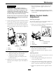
7.Ifadjustmentisnecessary,loosenthejamnut
fromtheyokeonthesidethatneedsadjustment.
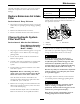
Removethehairpinandclevispin(see
Figure27).
Figure27
1.Hairpin3.Yoke
2.Clevispin
4.Jamnut
•AdjustingtheBraketoEngage:Shortenthe
linkagebyturningtheyokeclockwise.
•AdjustingtheBraketoDisengage:
Lengthenthelinkagebyturningtheyoke
counterclockwise.
8.Reinstalltheclevispinandhairpinandtighten
downthejamnut.Repeatstep6andreadjustif
necessary.
9.Whenadjustmentiscomplete,removethejack
standsorequivalentsupportandlowerthe
machine.
10.Placethemachineintothe“operating”position.
RefertotheDriveWheelReleaseValvessection
inOperation.
MotionControlHandle
Adjustment
Adjustingtheheight:
Themotioncontrolleverscanbeadjustedhigheror
lowerformaximumoperatorcomfort.
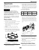
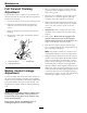
1.Removethehardwareholdingthecontrolleverto
thecontrolarmshaft(Figure28).
Figure28
1.Bolts
4.Controlarmshaft
2.Washer
5.Slottedhole
3.Controllever
2.Movethecontrollevertothenextsetofholes.
Securetheleverwiththehardware.
3.Repeattheadjustmentfortheoppositecontrol
lever.
AdjustingtheTilt
Themotioncontrolleverscanbetiltedforeoraftfor
maximumoperatorcomfort.
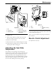
1.Loosentheupperboltholdingthecontrollever
tothecontrolarmshaft.
2.Loosenthelowerboltjustenoughtopivotthe
controlleverforeoraft
Figure28.Tightenboth
boltstosecurethecontrolinthenewposition.
3.Repeattheadjustmentfortheoppositecontrol
lever.
37