PIONEER E-SERIES For Serial Nos. 312,000,000 & Higher Part No. 4500-996 Rev.
WARNING CALIFORNIA Proposition 65 Warning The engine exhaust from this product contains chemicals known to the State of California to cause cancer, birth defects, or other reproductive harm. Important: The engine in this product is not equipped with a spark arrester muffler. It is a violation of California Public Resource Code (CPRC) Section 4442 to use or operate this engine on any forest-covered, brush-covered, or grass-covered land as defined in CPRC 4126.
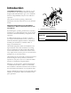
Introduction CONGRATULATIONS on the purchase of your Exmark Mower. This product has been carefully designed and manufactured to give you a maximum amount of dependability and years of trouble-free operation. This manual contains operating, maintenance, adjustment, and safety instructions for your Exmark mower. BEFORE OPERATING YOUR MOWER, CAREFULLY READ THIS MANUAL IN ITS ENTIRETY. Figure 1 1.
Contents Motion Control Linkage Adjustment ..............38 Adjusting the Seat Ride Suspension.................39 Electric Clutch Adjustment.............................39 Cleaning ............................................................40 Clean Engine and Exhaust System Area ...........................................................40 Remove Engine Shrouds and Clean Cooling Fins...............................................40 Clean Hydro Fan Cooling Fins ........................
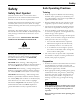
Safety Safety Safe Operating Practices Safety Alert Symbol Training • Read the Operator’s Manual and other training material. If the operator(s) or mechanic(s) can not read English it is the owner’s responsibility to explain this material to them. • Become familiar with the safe operation of the equipment, operator controls, and safety signs. • All operators and mechanics should be trained. The owner is responsible for training the users.
Safety • Inspect the area where the equipment is to be used and remove all rocks, toys, sticks, wires, bones, and other foreign objects which can be thrown by the machine and may cause personal injury to the operator or bystanders. DANGER In certain conditions during fueling, static electricity can be released causing a spark which can ignite gasoline vapors. A fire or explosion from gasoline can burn you and others and cause property damage.
Safety Operation damage and make repairs before restarting and operating the mower). WARNING – Before clearing blockages. Operating engine parts, especially the muffler, become extremely hot. Severe burns can occur on contact and debris, such as leaves, grass, brush, etc. can catch fire. • Allow engine parts, especially the muffler, to cool before touching. • Remove accumulated debris from muffler and engine area.
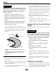
Safety • Be aware that operating on wet grass, across steep slopes or downhill may cause the mower to lose traction. Loss of traction to the drive wheels may result in sliding and a loss of braking and steering. • Always avoid sudden starting or stopping on a slope. If tires lose traction, disengage the blades and proceed slowly off the slope. • Follow the manufacturer’s recommendations for wheel weights or counter weights to improve stability. • Use extreme care with grass catchers or attachments.
Safety • Keep engine and engine area free from accumulation of grass, leaves, excessive grease or oil, and other debris which can accumulate in these areas. These materials can become combustible and may result in a fire. DANGER Battery electrolyte contains sulfuric acid, which is poisonous and can cause severe burns. Swallowing electrolyte can be fatal or if it touches skin can cause severe burns.
Safety WARNING Hydraulic fluid escaping under pressure can penetrate skin and cause injury. Fluid accidentally injected into the skin must be surgically removed within a few hours by a doctor familiar with this form of injury or gangrene may result. • If equipped, make sure all hydraulic fluid hoses and lines are in good condition and all hydraulic connections and fittings are tight before applying pressure to hydraulic system.
Safety Safety and Instructional Decals • New safety signs may be obtained from your authorized Exmark equipment dealer or distributor or from Exmark Mfg. Co. Inc. • Keep all safety signs legible. Remove all grease, dirt and debris from safety signs and instructional labels. • Replace all worn, damaged, or missing safety signs. • When replacement components are installed, be sure that current safety signs are affixed to the replaced components.
Safety 109-6014 116-1119 107-2102 116-1496 109-3148 116-3303 12
Safety 116-6363 1. Rotate the drive release knob to loosen, slide the knob, and tighten. 2. Push the machine. 116-4308 1. Latch 2. Unlatch PTO Switch Symbols 1. PTO–disengage 116-4465 1. Fast 2. Slow 3. Choke-on 4. Choke-off 13 2.
Safety 109-6016 1. Read the instructions before servicing or performing maintenance 2. Time interval 4. Refer to the Operator's manual for grease instructions 5. Check hydraulic oil level and refer to the Operator's manual or further instructions 6. Check tire pressure 3. Check oil level 116-4430 1. Park brake — engage 4. Neutral 2. Fast 3. Slow 5.
Specifications Specifications Model Numbers Serial Nos: 312,000,000 and Higher PNE651KA482; PNE691KA522 Systems • Battery Type: BCI Group U1 • Recommended Minimum Battery CCA: 260 CCA Engine • Battery Voltage: 12 Volt • Engine Specifications: See your Engine Owner’s Manual • Engine Oil Type: Exmark 4–Cycle Premium Engine Oil • RPM: Full Speed: 3600 ±50 RPM (PTO not engaged) Idle: 1500 ±100 RPM • Polarity: Negative Ground • Fuses: All units: – 25 amp main fuse – 20 amp charging system fuse Fuel Syste
Specifications • • • • • Tires & Wheels – Moving motion control levers outward (in slots) locks the drive system in neutral. PTO Engagement Switch: Engages electric clutch (to drive belt) which engages mower blades. Parking Brake Lever: Engages parking brake. Deck Height Adjustment Lever: Sets cutting height to desired position. Deck Lift Pedal: Foot pedal that lifts deck. Transport Lock: Latching position: Automatically latches at the transport position.
Specifications Dimensions Torque Requirements Overall Width: 48 inch Deck 52 inch Deck Bolt Location Torque Blade Drive Sheave Mounting Nut 75-85 ft-lb (102-115 N-m) 50-60 ft-lb (68-81 N-m) Without Deck 44.1 inches (112.0 44.1 inches (112.0 cm) cm) Deflector Up 48.0 inches (121.9 52.8 inches (134.1 cm) cm) Blade Mounting Bolt (lubricate with anti-seize) Anti-Scalp Roller Nyloc Nut See Figure 18 Deflector Down 59.2 inches (150.4 64.0 inches (162.
Operation Product Overview Operation Note: Determine the left and right sides of the machine from the normal operating position. Controls Motion Control Levers The motion control levers located on each side of the console control the forward and reverse motion of the machine. Moving the levers forward or backward turns the wheel on the same side forward or reverse respectively. Wheel speed is proportional to the amount the lever is moved.
Operation rear, to the detent, will put the choke in the “OFF” position. Do Not run a warm engine with choke in the “ON” position. The ignition switch is used to start and stop the engine. The switch has three positions “OFF”, “ON” and “START”. Insert key into switch and rotate clockwise to the “ON” position. Rotate clockwise to the next position to engage the starter (key must be held against spring pressure in this position).
Operation The fuel shut-off valve is used to shut off the fuel when the machine will not be used for a few days, during transport to and from the jobsite, and when parked inside a building. Align valve handle with the fuel line to open. Rotate 90° to close. Drive Wheel Release Valves WARNING Hands may become entangled in the rotating drive components below the engine deck, which could result in serious injury or death.
Operation Switch must be pulled out (up) to engage the blades. Switch is pushed in to disengage the blades. Make sure you understand the controls, their locations, their functions, and their safety requirements. Deck Lift Pedal Refer to the Maintenance section and perform all the necessary inspection and maintenance steps. Located at the right front corner of the floor pan. Push the pedal forward with your foot to raise the cutting deck.
Operation Starting the Engine 1. Move the motion control levers out to the neutral lock position. 2. Pull up and back on the parking brake lever to engage the parking brake. 3. Push down on the PTO switch to the “disengage” position. Note: It is not necessary for the operator to be in the seat to start the engine. 4. Place the throttle midway between the “SLOW” and “FAST” positions. 5. On a cold engine, push the choke lever forward into the “ON” position.
Operation Important: To begin movement (forward or backward) the operator must be in the seat, the brake lever must be disengaged (pushed down) before the motion control levers can be moved in or the engine will stop. The PTO push-pull switch engages the cutting blades. Be sure that all persons are clear of the mower deck and discharge area before engaging PTO. Important: Operator must be in seat before the PTO can be engaged.
Operation To turn right, release pressure on the RH motion control lever and the rear of the machine will move towards the rear and to the right. To turn left, release pressure on the LH motion control lever and the rear of the machine will move towards the rear and to the left. 3. To stop, position both motion control levers in the neutral operate position. Adjusting the Cutting Height The cutting height of the mower deck is adjusted from 1 1/2 to 5 inches (3.8 cm to 12.7 cm) in 1/4 inch (6.
Operation Adjusting the Anti-Scalp Rollers 8. Torque the 3/8–16 whizlock nut to 27-33 ft-lb (37-45 N-m) (Figure 18). It is recommended to change the anti-scalp roller position, when the height of cut has changed. 9. Torque the 3/8 nyloc nut to 27-33 ft-lb (37-45 N-m). 1. Stop the machine and move the motion control levers outward to the neutral locked position. 2. Disengage the PTO. 3. Engage the park brake. 4. Stop the engine, remove the key and wait for all moving parts to stop. 5.
Operation WARNING Loading a unit on a trailer or truck increases the possibility of backward tip-over. Backward tip-over could cause serious injury or death. • Use extreme caution when operating a unit on a ramp. • Use only a single, full width ramp; Do Not use individual ramps for each side of the unit. • If individual ramps must be used, use enough ramps to create an unbroken ramp surface wider than the unit. • Do Not exceed a 15° angle between ramp and ground or between ramp and trailer or truck.
Maintenance Maintenance Note: Determine the left and right sides of the machine from the normal operating position. WARNING WARNING While maintenance or adjustments are being made, someone could start the engine. Accidental starting of the engine could seriously injure you or other bystanders. The engine can become very hot. Touching a hot engine can cause severe burns. Allow the engine to cool completely before service or making repairs around the engine area.
Maintenance Periodic Maintenance the table and charge the battery for the recommended time interval to bring the charge up to a full charge of 12.6 volts or greater. Check Engine Oil Level Important: Make sure the negative battery cable is disconnected and the battery charger used for charging the battery has an output of 16 volts and 7 amps or less to avoid damaging the battery (see chart for recommended charger settings). Service Interval: Before each use or daily 1.
Maintenance DANGER Jump starting a weak battery that is cracked, frozen, has low electrolyte level, or an open/shorted battery cell, can cause an explosion resulting in serious personal injury. Do Not jump start a weak battery if these conditions exist. 2. Make sure the booster is a good and fully charged lead acid battery at 12.6 volts or greater. Use properly sized jumper cables (4 to 6 AWG) with short lengths to reduce voltage drop between systems.
Maintenance Note: To prevent engine cut-outs on rough terrain the seat kill switch has a 1/2 second delay. 1. Check starting circuit. Starter should crank with, parking brake engaged, PTO disengaged and motion control levers moved out in the neutral lock position. The operator does not need to be in the seat to start the engine. Try to start with operator in seat, parking brake disengaged, PTO disengaged and motion control levers in the neutral lock position - starter must not crank.
Maintenance Service Air Cleaner Important: It is essential that operator safety mechanisms be connected and in proper operating condition prior to use for mowing. Service Interval: Every 100 hours—Check the air cleaner; replace if dirty or damaged. (May need more often under severe conditions. See the Engine Owner's Manual for additional information.) 1. Stop engine, wait for all moving parts to stop, and remove key. Engage parking brake. 2. See the Engine Owner's Manual for maintenance instructions.
Maintenance 1. Stop engine and wait for all moving parts to stop. Engage parking brake. 1. Stop engine, wait for all moving parts to stop, and remove key. Engage parking brake. 2. Wait until the unit cools before checking the hydraulic oil. 2. Lubricate fittings with one to two pumps of NGLI grade #2 multi-purpose gun grease. 3. Check expansion tank and if necessary add Exmark Premium Hydro Oil to the FULL COLD line (see Figure 22).
Maintenance originally installed at the factory to keep the fuel line away from components that could cause fuel line damage. Hydro Oil Change Interval Exmark Premium Hydro Oil (Preferred) 500 Hours Replace Emissions Air Intake Filter Mobil 1 15W50 250 Hours Torque plugs to 180 in-lb (244 N-m). Continue to add oil until it reaches the FULL COLD line on the expansion reservoir. Service Interval: Every 500 hours 1. Stop engine, wait for all moving parts to stop, and remove key or spark plug wire(s).
Maintenance Thread Locking Adhesives A. With the bypass valve open and the engine running, slowly move the directional control in both forward and reverse (5 or 6 times). Thread locking adhesives such as “Loctite 242” or “Fel-Pro, Pro-Lock Nut Type” are used on the following fasteners: B. With the bypass valve closed and the engine running, slowly move the directional control in both forward and reverse directions (5 to 6 times). Check the oil level, and add oil as required after stopping the engine.
Maintenance Adjustments 8. Set the height-of-cut lever to the 3 inch (76 mm) position. Place two “B” thick blocks (see Block Height and Rake Table) under the rear edge of the cutting deck skirt; one on each side of the cutting deck. Place two “A” thick blocks under each side of the front edge of the deck, but not under the anti-scalp roller brackets.
Maintenance “R” (see Block Height and Rake Table in Deck Leveling) lower than the rear blade tip, adjust the blade level using the following instructions: 2. Park the machine on a level surface and disengage the blade control switch. 3. Move the motion control levers outward to the neutral position, engage the parking brake, stop the engine, remove the key, and wait for all moving parts to stop before leaving the operating position. 4. Check the air pressure of all four tires.
Maintenance 9. When adjustment is complete, remove the jack stands or equivalent support and lower the machine. CAUTION Raising the mower deck for service or maintenance relying solely on mechanical or hydraulic jacks could be dangerous. The mechanical or hydraulic jacks may not be enough support or may malfunction allowing the unit to fall, which could cause injury. 10. Place the machine into the “operating” position. Refer to the Drive Wheel Release Valves section in Operation.
Maintenance Full Forward Tracking Adjustment 1. Prior to starting the engine, push the deck lift pedal and remove the height of cut pin. Lower deck to the ground. If the machine travels or pulls to one side when the motion control levers are in the full forward position, adjust the cover plates. 2. Raise the rear of machine up and support with jack stands (or equivalent support) just high enough to allow drive wheels to turn freely. 1. Loosen the screws on a cover plate (see Figure 29). 3.
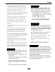
Maintenance Figure 31 1. Bolt 2. Spring Figure 30 1. Nut 4. Control plate 2. Turnbuckle 5. Return to neutral plate 3. Stationary plate 6. Tabs touching return to neutral plate 3. Nut 4. Additional mounting holes Up to five springs can be secured to the seat box with a nut and bolt, see Figure 31. Refer to the Parts Manual for spring and hardware part numbers. 8. Tighten nuts. 9. Shut off unit. Remove jumper wire from wire harness and plug connector into seat switch.
Maintenance Cleaning 1. Stop engine, wait for all moving parts to stop, and remove key. Engage parking brake. 2. Unlatch and flip the seat up. 3. Remove accumulated debris from the hydro fan cooling fins and upper surfaces. Clean Engine and Exhaust System Area Service Interval: Before each use or daily (May be required more often in dry or dirty conditions.) Clean Debris From Machine Service Interval: Before each use or daily 1. Stop engine, wait for all moving parts to stop, and remove key.
Maintenance recycling center or according to your state and local regulations. Battery Disposal DANGER Battery electrolyte contains sulfuric acid, which is poisonous and can cause severe burns. Swallowing electrolyte can be fatal or if it touches skin can cause severe burns. • Wear safety glasses to shield eyes, and rubber gloves to protect skin and clothing when handling electrolyte. • Do Not swallow electrolyte. • In the event of an accident, flush with water and call a doctor immediately.
Troubleshooting Troubleshooting Important: It is essential that all operator safety mechanisms be connected and in proper operating condition prior to mower use. When a problem occurs, do not overlook the simple causes. For example: starting problems could be caused by an empty fuel tank. The following table lists some of the common causes of trouble. Do not attempt to service or replace major items or any items that call for special timing of adjustment procedures (such as valves, governor, etc.).
Troubleshooting Problem Engine loses power Possible Cause Corrective Action 1. Engine load is excessive 1. Reduce the ground speed. 2. Air cleaner is dirty. 3. Oil level in the crankcase is low. 4. Cooling fins and air passages for the engine are plugged. 5. Dirt in fuel filter. 6. Dirt, water, or stale fuel is in the fuel system. 2. Clean or replace the air cleaner element. 3. Add oil to the crankcase. 4. Remove the obstructions from the cooling fins and air passages. 5. Replace the fuel filter. 6.
Schematics Schematics Electrical Diagram 44
Schematics Electrical Logic Schematic 45
Pioneer E-Series Turf Equipment 1 Year Limited Commercial Warranty 4 Year or 500 Hours Limited Consumer Warranty General Warranty Conditions and Products Covered Exmark Mfg. Co. Inc. and its affiliate, Exmark Warranty Company, pursuant to an agreement between them, jointly warrant on the terms and conditions herein, that we will repair, replace or adjust any part on these products and found by us (in the exercise of our reasonable discretion) to be defective in factory materials or workmanship.
Notes: 47
Notes: 48
Service Record Date: Description of Work Done: 49 Service Done By:
G011841 Figure 32 This page may be copied for personal use. 1. The maximum slope you can safely operate the machine on is 15 degrees. Use the slope indicator to determine the degree of slope of hills before operating. Do Not operate this machine on a slope greater than 15 degrees. Fold along the appropriate line to match the recommended slope. 2. Align this edge with a vertical surface, a tree, building, fence pole, etc. 3. Example of how to compare slope with folded edge.
SEE EXMARK’S COMPLETE LINE OF ACCESSORIES AND OPTIONS MID-MOUNT RIDING ACCESSORIES AND OPTIONS CUSTOM RIDE SEAT SUSPENSION SYSTEM OPERATOR CONTROLLED DISCHARGE FULL SUSPENSION SEAT ROLL OVER PROTECTION SYSTEM (ROPS) DECK LIFT ASSIST KIT SUN SHADE HITCH KIT TRASH CONTAINER LIGHT KIT TURF STRIPER 12V POWER PORT ULTRA VAC COLLECTION SYSTEM MICRO-MULCH SYSTEM ULTRA VAC QUICK DISPOSAL SYSTEM OUT-FRONT RIDING ACCESSORIES AND OPTIONS CUSTOM RIDE SEAT SUSPENSION SYSTEM SNOW BLADE DUAL-TAIL WHEEL SN