LAZER Z DS-SERIES ® For Serial Nos. 312,000,000 & Higher Lazer Z (LZDS) Units Part No. 4501-041 Rev.
WARNING CALIFORNIA Proposition 65 Warning The engine exhaust from this product contains chemicals known to the State of California to cause cancer, birth defects, or other reproductive harm. Important: The engine in this product is not equipped with a spark arrester muffler. It is a violation of California Public Resource Code (CPRC) Section 4442 to use or operate this engine on any forest-covered, brush-covered, or grass-covered land as defined in CPRC 4126.
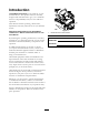
Introduction CONGRATULATIONS on the purchase of your Exmark Mower. This product has been carefully designed and manufactured to give you a maximum amount of dependability and years of trouble-free operation. This manual contains operating, maintenance, adjustment, and safety instructions for your Exmark mower. Figure 1 BEFORE OPERATING YOUR MOWER, CAREFULLY READ THIS MANUAL IN ITS ENTIRETY. 1.
Contents Dielectric Grease............................................40 Adjustments ......................................................40 Deck Leveling ................................................40 Pump Drive Belt Tension................................41 Deck Belt Tension ..........................................41 Mule Drive Belt Tension Adjustment ..............41 Alternator Belt Tension ..................................42 Belt Guide Adjustment ...................................
Safety Safety Safe Operating Practices Safety Alert Symbol Training • Read the Operator’s Manual and other training material. If the operator(s) or mechanic(s) can not read English it is the owner’s responsibility to explain this material to them. • Become familiar with the safe operation of the equipment, operator controls, and safety signs. • All operators and mechanics should be trained. The owner is responsible for training the users.
Safety • Inspect the area where the equipment is to be used and remove all rocks, toys, sticks, wires, bones, and other foreign objects which can be thrown by the machine and may cause personal injury to the operator or bystanders. WARNING Diesel fuel is harmful or fatal if swallowed. Long-term exposure to vapors has caused cancer in laboratory animals. Failure to use caution may cause serious injury or illness. • Avoid prolonged breathing of vapors.
Safety guards, switches and other devices in place and in proper working condition. • Be aware of the mower discharge path and direct discharge away from others. • Never mow with the discharge deflector raised, removed or altered unless there is a grass collection system or mulch kit in place and working properly. • Do Not operate the mower under the influence of alcohol or drugs. • Use extreme care when loading or unloading the machine into a trailer or truck.
Safety WARNING There is no rollover protection when the roll bar is down. Wheels dropping over edges, ditches, steep banks, or water can cause rollovers, which may result in serious injury, death or drowning. • Keep the roll bar in the raised and locked position and use seat belt. • Lower the roll bar only when absolutely necessary. • Do Not wear seat belt when the roll bar is down. • Drive slowly and carefully. • Raise the roll bar as soon as clearance permits. Figure 3 1.
Safety positive last. Reconnect positive first and negative last. CAUTION • Use care when checking blades. Wrap the blade(s) or wear gloves, and use caution when servicing them. Only replace damaged blades. Never straighten or weld them. If the ignition is in the “ON” position there is potential for sparks and engagement of components. Sparks could cause an explosion or moving parts could accidentally engage causing personal injury. • Keep hands and feet away from moving parts.
Safety WARNING Hydraulic fluid escaping under pressure can penetrate skin and cause injury. Fluid accidentally injected into the skin must be surgically removed within a few hours by a doctor familiar with this form of injury or gangrene may result. • If equipped, make sure all hydraulic fluid hoses and lines are in good condition and all hydraulic connections and fittings are tight before applying pressure to hydraulic system.
Safety Safety and Instructional Decals • New safety signs may be obtained from your authorized Exmark equipment dealer or distributor or from Exmark Mfg. Co. Inc. • Keep all safety signs legible. Remove all grease, dirt and debris from safety signs and instructional labels. • Replace all worn, damaged, or missing safety signs. • When replacement components are installed, be sure that current safety signs are affixed to the replaced components.
Safety 103-2076 103-0223 103-7218 103-0261 103-1798 107-2102 12
Safety 109-0872 109-1399 109-1214 109-2219 109-1215 109-2263 13
Safety 109-2264 109-2478 109-2951 109-3148 14
Safety 116-0127 116-3303 116-5074 116-0404 116-5185 1. PTO–engage 2.
Safety 19426-87881 19426-87903 107-9866 1. Fast 2. Slow 3. Neutral 4.
Specifications Specifications Model Numbers Serial Nos: 312,000,000 and Higher LZDS902K605; LZDS902K725 Systems • Operator must be in seat when PTO is engaged, brake is disengaged, or motion control levers are moved in or engine will stop. • Engine will stop if either the left, the right, or both levers are moved from neutral lock position while brake is engaged.
Specifications • • • • – Moving motion control levers outward (in slots) locks the drive system in neutral. PTO Engagement Switch: Engages electric clutch (to drive belt) which engages mower blades. Parking Brake Lever: Engages parking brake. Deck Height Adjustment Lever: Sets cutting height to desired position. Deck Lift Assist Pedal: Foot pedal that assists in raising the deck. Drive Tread Size “Multi-Trac C/S” Smooth Size 26 x 12.00-12 Ply Rating 4 Pressure 10 psi (69 kPa) 13 x 6.
Specifications Dimensions Torque Requirements Overall Width: 60 inch Deck 72 inch Deck Bolt Location Torque Blade Drive Sheave Mounting Nut 90-110 ft-lb (122-149 N-m) Without Deck 53.5 inches (135.9 61.5 inches (156.2 cm) cm) Cutter Housing Spindle Nut 160-185 ft-lb (217-251 N-m) Deflector Up 61.4 inches (156.0 74.3 inches (188.7 cm) cm) Blade Mounting Bolt (lubricate with anti-seize) 55-60 ft-lb (75-81 N-m) Deflector Down 72.8 inches (184.9 85.8 inches (217.
Operation Product Overview Operation Note: Determine the left and right sides of the machine from the normal operating position. Controls Motion Control Levers The motion control levers located on each side of the console control the forward and reverse motion of the machine. Moving the levers forward or backward turns the wheel on the same side forward or reverse respectively. Wheel speed is proportional to the amount the lever is moved.
Operation The valve has three positions, each position made in 1/4 turn increments. and moving the throttle lever to the rear will decrease engine speed. Moving the throttle forward into the detent is full throttle. Fuel Flow Valve Handle Position Brake Lever “Off ” Right Located on left side of unit, just to the front of the console. Right Tank Down Left Tank Left The brake lever engages a parking brake on the drive wheels. Fuel Gauge Pull the lever up and rearward to engage the brake.
Operation PTO Engagement Switch Warning Buzzer Located on right fuel tank. Located behind the seat under the air deflector on the electrical panel. Switch must be pulled out (up) to engage the blades. Switch is pushed in to disengage the blades. The buzzer is a warning signal that the engine is overheating or the oil pressure is low. See the Troubleshooting section. Note: If the engine overheats, the PTO will automatically disengage. The PTO cannot be engaged until the engine has cooled down.
Operation Important: Do Not use kerosene or gasoline instead of diesel fuel. Failure to observe this caution will damage the engine. rear part of the seat is secured with the seat latch. Do Not overfill fuel tank. Fill the fuel tank to the bottom of the filler neck. The empty space in the tank allows the fuel to expand. Overfilling may result in fuel leakage or damage to the engine or emission system. If possible, fill the fuel tank after each use.
Operation 7. Turn ignition switch to the “ON” position. Depress the glow plug switch and the glow plug light will turn on. Hold switch as required by chart below. Turn the ignition switch to the “START” position. Release the ignition switch as soon as the engine starts. DANGER An uncovered discharge opening will allow objects to be thrown in an operator’s or bystander’s direction. Also, contact with the blade could occur. Thrown objects or blade contact can cause serious injury or death.
Operation Driving the Machine 3. To move forward in a straight line, move both levers forward with equal pressure. CAUTION Machine can spin very rapidly by positioning one lever too much ahead of the other. Operator may lose control of the machine, which may cause damage to the machine or injury. • Use caution when making turns. • Slow the machine down before making sharp turns.
Operation To turn right, release pressure on the RH motion control lever and the rear of the machine will move towards the rear and to the right. See the decal on the side of the deck lift plate for cut heights. 5. Move the deck height lever out of the transport position (or 5 inch (12.7 cm) cutting height) and down onto the height adjustment pin to mow at selected height. To turn left, release pressure on the LH motion control lever and the rear of the machine will move towards the rear and to the left.
Operation 7. Be sure the roller bolts are installed with the spring disc washer between the head of the bolt and the mounting bracket. CAUTION This unit does not have proper turn signals, lights, reflective markings, or a slow moving vehicle emblem. Driving on a street or roadway without such equipment is dangerous and can lead to accidents causing personal injury.
Operation truck. Steeper angles may also cause the unit to tip backward. If loading on or near a slope, position the trailer or truck so it is on the down side of the slope and the ramp extends up the slope. This will minimize the ramp angle. The trailer or truck should be as level as possible. Important: Do Not attempt to turn the unit while on the ramp, you may lose control and drive off the side. Avoid sudden acceleration when driving up a ramp and sudden deceleration when backing down a ramp.
Maintenance Maintenance Note: Determine the left and right sides of the machine from the normal operating position. WARNING WARNING While maintenance or adjustments are being made, someone could start the engine. Accidental starting of the engine could seriously injure you or other bystanders. The engine can become very hot. Touching a hot engine can cause severe burns. Allow the engine to cool completely before service or making repairs around the engine area.
Maintenance Maintenance Service Interval Maintenance Procedure Every 500 hours • • • • Every 600 hours • Replace the air cleaner elements. (May need more often under severe conditions. See the Engine Owner's Manual for additional information.) Every 4,000 hours Monthly Yearly Check the wheel hub slotted nut torque specifications. Check the wheel lug nuts. Change the hydraulic filter (Every 250 hours/yearly if using Mobil 1 15W50) Check the park brake adjustment. • Change engine coolant.
Maintenance 7 amps or less to avoid damaging the battery (see chart for recommended charger settings). Voltage Reading Percent Charge Maximum Charger Settings Charging Interval 12.6 or greater 100% 16 volts/7 amps No Charging Required 12.4 – 12.6 75–100% 16 volts/7 amps 30 Minutes 12.2 – 12.4 50–75% 16 volts/7 amps 1 Hour 12.0–12.2 25–50% 14.4 volts/4 2 Hours amps 11.7–12.0 0–25% 14.4 volts/4 3 Hours amps 11.7 or less 0% 14.
Maintenance Figure 14 1. Install bushing in blade prior to installing bushing in spindle. Figure 13 1. Positive (+) cable on discharged battery B. Install bushing/blade assembly into spindle. 2. Positive (+) cable on booster battery 3. Negative (–) cable on the booster battery 4. Negative (–) cable on the engine block 5. Booster battery 6. Discharged battery 7. Engine block 4. Connect the other end of the positive cable to the positive terminal of the booster battery. 5.
Maintenance Run engine at one-third throttle, with brake disengaged, move levers in and raise off seat (but do not get off of machine) engine must initiate shutdown after 1/2 second has elapsed. WARNING Incorrect installation of the blade or components used to retain the blade can be dangerous. Failure to use all original components and assembled as shown could allow a blade or blade component to be thrown out from under the deck resulting in serious personal injury or death.
Maintenance 1. 2. 3. 4. 5. 6. 7. the Engine Owner's Manual for additional information.) Every 600 hours— Replace the air cleaner elements. (May need more often under severe conditions. See the Engine Owner's Manual for additional information.) Stop engine, wait for all moving parts to stop, and remove key. Engage parking brake. Unhook two air filter canister latches to gain access to the air cleaner element. Remove air cleaner canister cover and remove outer element.
Maintenance 2. Check tire pressure in drive tires. 3. Inflate drive tires to 10 psi (69 kPa). 4. Semi-pneumatic caster tires do not need to be inflated. Lubrication Chart Fitting Locations Note: Do Not add any type of tire liner or foam fill material to the tires. Excessive loads created by foam filled tires may cause failures to the hydro drive system, frame, and other components. Foam filling tires will void the warranty. Check Condition Of Belts Service Interval: Every 40 hours 1.
Maintenance Wheel Hub - Slotted Nut Torque Specification Not thread spacer nut all of the way onto the end of the axle. Leave approximately 1/8 inch (3 mm) from the outer surface of the spacer nut to the end of the axle inside the nut. Service Interval: After the first 100 hours Every 500 hours thereafter 9. Insert the assembled nut and axle into the wheel on the side of the wheel with the new seal and bearing. Torque the slotted nut to 211-260 ft-lb (286-352 N-m). 10.
Maintenance Change Inline Fuel Filter (bushings are located to the inside of the flange bearings). Service Interval: As required Lubricate Motion Control Bronze Bushings An inline fuel filter is installed between the fuel tank and the fuel pump. Replace when necessary. Replacement Filters Service Interval: Every 160 hours Exmark P/N 112-7836 1. Stop engine, wait for all moving parts to stop, and remove key. Engage parking brake. Change Hydraulic System Filter 2. Unhook seat latch and tilt seat up.
Maintenance 6. Raise the rear of machine up and support with jack stands (or equivalent support) just high enough to allow drive wheels to turn freely. CAUTION Engine coolant is toxic. Swallowing coolant can cause poisoning. 7. Start engine and move throttle control ahead to full throttle position. Move the speed control levers to the full speed and run for several minutes. Shut down machine and recheck oil level. • Do Not swallow. • Keep out of reach of children and pets.
Maintenance core. As air is purged from the engine block and the coolant level drops, add additional coolant to the radiator. 8. When the radiator is completely full and no additional coolant can be added, continue running and install the radiator cap. Make sure that the cap is completely seated by pressing down firmly while turning until the cap stops. Once the cap is installed, the engine may be stopped. Check Spark Arrester (if equipped) Service Interval: Every 50 hours Figure 17 1.
Maintenance Adjustments • Fuel tank bulkhead fitting nuts. • Bolts retaining stub shaft to engine flywheel. Note: Disengage PTO, shut off engine, wait for all moving parts to stop, engage parking brake, and remove key before servicing, cleaning, or making any adjustments to the unit. Adhesives such as “Loctite RC/609 or RC/680” or “Fel-Pro Pro-Lock Retaining I or Retaining II” are used on the following: Fuel tank studs, where studs are inserted into tank.
Maintenance Pump Drive Belt Tension the chain bolts in the deck lift arms making sure they don’t move while tightening. Self-tensioning - No adjustment necessary. 9. Loosen the four nuts which secure the front swivels (two per side) until the front chains are loose and front of deck is supported by the 3/4 inch (19 mm) block. Do Not loosen the front chain hardware. Deck Belt Tension Self-tensioning - No adjustment necessary. 10.
Maintenance Belt Guide Adjustment 1. Stop engine, wait for all moving parts to stop, and remove key. Engage parking brake. 2. Remove the belt shield on the right side of mower deck. 3. Note belt guide bolted to deck near the shield support stud and right-hand pulley. Guide should be 1/8 inch (3.2 mm) away from the belt, with bolt-end of guide near end of slot (Figure 21). 4. If adjustment is necessary, loosen the bolt securing the belt guide and make proper adjustment. Tighten hardware. Figure 19 1.
Maintenance spring. Clearance should measure 1/8 to 3/16 inch (3.2-4.8 mm). If necessary, adjust the nyloc nut accordingly. 12. If the correct gap can no longer be achieved because there is no clearance between the nyloc nut below the spring and the jam nut, or there are no threads left in the bottom nyloc nut, the length of the brake rod can be adjusted. Remove a pin from a yoke at either end of the brake rod and lengthen (or shorten) the brake rod until the correct gap can be achieved. 13.
Maintenance Electric Clutch Adjustment No adjustment necessary. However when the clutch brake has worn to the point where the clutch no longer engages consistently, the shim can be removed to extend the clutch life. Figure 24 1. Brake mounting bolt B. Using needle nose pliers, or by hand, take hold of the tab and remove the shim (Do Not discard the shim until proper clutch function has been confirmed). Figure 23 1. Armature 5. Brake spacer 2. Field shell 6. Re-gap shim 3. Rotor 7. Brake pole 2.
Maintenance 5. If adjustment is needed, loosen the nut against the yoke and while applying slight rearward pressure on the motion control lever, turn the head of the adjustment bolt in the appropriate direction until lever is centered (keeping rearward pressure on the lever will keep the pin at the end of the slot and allow the adjustment bolt to move the lever to the appropriate position). Tighten lock nut. 6. Repeat on opposite side of unit. Figure 26 1. Feeler gauge • If the gap is less than 0.
Maintenance because of the jumper wire being used. Run engine at full throttle and release brake. CAUTION Raising the mower deck for service or maintenance relying solely on mechanical or hydraulic jacks could be dangerous. The mechanical or hydraulic jacks may not be enough support or may malfunction allowing the unit to fall, which could cause injury. 7. The reverse indicator spring must be correct before the following adjustments can be made. See the Reverse Indicator Adjustment section.
Maintenance Motion Control Damper Adjustment The top damper mounting bolt can be adjusted to obtain a more desired motion control lever resistance. See Figure 30 for mounting options. Figure 31 1. Spring disc washers Figure 30 1. Motion control bracket 2. Least resistance (softest feel) 3. Medium resistance (medium feel) 4. Most resistance (firmest feel) 5. Torque nyloc nut to 200 in-lb (16.7 ft-lb). Bolt must protrude past end of nyloc nut after torque. 6. Damper 7. Damper must move freely on bolt.
Maintenance Cleaning CAUTION Excessive debris around engine and exhaust system area can cause engine, exhaust area, and hydraulic system to overheat which can create a fire hazard. Clean Engine Cooling System Clean all debris from engine and exhaust system area. Service Interval: Before each use or daily (May be required more often in dry or dirty conditions.) 1. Stop engine, wait for all moving parts to stop, and remove key. Engage parking brake. 2. Remove air deflector panel from behind seat. 3.
Maintenance Battery Disposal Clean Debris From Machine Service Interval: Before each use or daily DANGER 1. Stop engine, wait for all moving parts to stop, and remove key. Engage parking brake. Battery electrolyte contains sulfuric acid, which is poisonous and can cause severe burns. Swallowing electrolyte can be fatal or if it touches skin can cause severe burns. 2.
Troubleshooting Troubleshooting Important: It is essential that all operator safety mechanisms be connected and in proper operating condition prior to mower use. When a problem occurs, do not overlook the simple causes. For example: starting problems could be caused by an empty fuel tank. The following table lists some of the common causes of trouble. Do not attempt to service or replace major items or any items that call for special timing of adjustment procedures (such as valves, governor, etc.).
Troubleshooting Problem Engine overheats. Possible Cause Corrective Action 1. Engine load is excessive. 1. Reduce the ground speed. 2. 3. 4. 5. 2. 3. 4. 5. Oil level in the crankcase is low. Dirty air filter. Coolant level is low. Debris on or around radiator. 6. Water pump or alternator belt is worn, loose, or broken. Add oil to the crankcase. Clean or replace the air cleaner element. Add coolant. Remove debris (see Clean the Radiator section in Maintenance). 6.
Troubleshooting Problem Warning buzzer emits continuous beep. (See also Engine overheats). Warning buzzer emits intermittent beep. Clutch will not engage. Possible Cause Corrective Action 1. Temperature is increasing on coolant temperature gauge. 1. Turn unit off and allow engine and engine components to cool. 2. Coolant level is low. 3. Debris on or around radiator. 4. Water pump or alternator belt is worn, loose or broken. 2. Add coolant. 3. Remove debris. 4. Contact Authorized Service Dealer. 1.
HOUR METER, AUX HYD, PTO SWITCH TERMINAL X TERMINAL Y 53 3. START 2. RUN 1.
Schematics Electrical Schematic 54
Exmark Commercial Turf Equipment 2 Year Limited Warranty If for any reason you are dissatisfied with the Service Dealer’s analysis or with the assistance provided, contact us at: Exmark Customer Service Department The Exmark Warranty Company 2101 Ashland Avenue Beatrice, NE 68310 402-223-6375 or service@exmark.com Conditions and Products Covered Exmark Mfg. Co. Inc.
Notes: 56
Service Record Date: Description of Work Done: 57 Service Done By:
G011841 Figure 32 This page may be copied for personal use. 1. The maximum slope you can safely operate the machine on is 15 degrees. Use the slope indicator to determine the degree of slope of hills before operating. Do Not operate this machine on a slope greater than 15 degrees. Fold along the appropriate line to match the recommended slope. 2. Align this edge with a vertical surface, a tree, building, fence pole, etc. 3. Example of how to compare slope with folded edge.
SEE EXMARK’S COMPLETE LINE OF ACCESSORIES AND OPTIONS MID-MOUNT RIDING ACCESSORIES AND OPTIONS CUSTOM RIDE SEAT SUSPENSION SYSTEM OPERATOR CONTROLLED DISCHARGE FULL SUSPENSION SEAT ROLL OVER PROTECTION SYSTEM (ROPS) DECK LIFT ASSIST KIT SUN SHADE HITCH KIT TRASH CONTAINER LIGHT KIT TURF STRIPER 12V POWER PORT ULTRA VAC COLLECTION SYSTEM MICRO-MULCH SYSTEM ULTRA VAC QUICK DISPOSAL SYSTEM OUT-FRONT RIDING ACCESSORIES AND OPTIONS CUSTOM RIDE SEAT SUSPENSION SYSTEM SNOW BLADE DUAL-TAIL WHEEL SN