
Mfg. Co. Inc. Lawn Mower User Manual

Maintenance
18.Rotatethedrivewheelreleasehandletothe
“operating”position.RefertotheDriveWheel
ReleaseValvessectioninOperation.
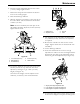
19.Installthereartiresandtorquelugnutsto90-95
ft-lb(122-129N-m).
20.Removejackstands.
ElectricClutchAdjustment
Noadjustmentnecessary;howeversomelatermodel
yearunitshavebeenbuiltwithclutchesthatcontaina
brakeshim.Whentheclutchbrakehasworntothe
pointwheretheclutchnolongerengagesconsistently,
theshimcanberemovedtoextendtheclutchlife.
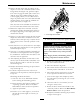
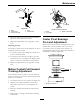
Figure35
1.Armature5.Brakespacer
2.Fieldshell6.Re-gapshim
3.Rotor7.Brakepole
4.Brakemountingbolt
RemovingtheShim:
1.Stopengine,waitforallmovingpartstostop,
andremovekey.Engageparkingbrake.Allow
themachinetocoolcompletelybeforestarting
theseinstructions.
2.Usingapneumaticline,blowoutanydebris
fromunderthebrakepoleandaroundthebrake
spacers.
3.Checktheconditionofthewireharnessleads,
connectors,andterminals.Cleanorrepairas
necessary.
4.Verifythat12Vispresentattheclutchconnector
whenthePTOswitchisengaged.
5.Measurethegapbetweentherotorandarmature.
Ifthegapisgreaterthan.04inch(1mm),proceed
withthefollowingsteps:
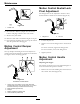
A.Loosenbothbrakemountingboltsone-half
toonefullturn(seeFigure36).
Note:DoNotremovethebrakepolefrom
theeldshell/armature.Thebrakepolehas
worntomatchthearmatureandneedsto
continuetomatchaftertheshimisremoved
toensureproperbraketorque.
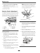
Figure36
1.Brakemountingbolt
2.Shim
B.Usingneedlenosepliers,orbyhand,take
holdofthetabandremovetheshim(DoNot
discardtheshimuntilproperclutchfunction
hasbeenconrmed).
C.Usingapneumaticline,blowoutanydebris
fromunderthebrakepoleandaroundthe
brakespacers.
D.Re-torqueeachbolt(M6x1)to10ft-lb(13
N-m)+/-0.5ft-lb(0.7N-m).
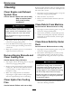
E.Usinga0.010inchthickfeelergauge,verify
thatagapispresentbetweentherotorand
armaturefaceonbothsidesofthebrakepole
asshown.(Duetothewaytherotorand
armaturefaceswear(peaksandvalleys)itis
sometimesdifculttomeasurethetruegap.)
G011733
1
Figure37
1.Feelergauge
44