
Mfg. Co. Inc. Lawn Mower User Manual

Maintenance
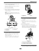
6.Inserttheheightadjustmentpinintothe3inch
(7.6cm)cuttingheightlocation.
7.Releasethetransportlockandallowthedeckto
lowertothecuttingheight.
8.Raisethedischargedeector.
9.Measurefromthelevelsurfacetothefronttipof
thecenterblade.Themeasurementshouldread
3inches(7.6mm).
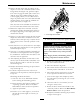
Note:Inmostconditions,thebacktipsonthe
sidebladesshouldbeadjusted1/4inch(6.4mm)
higherthanthefront.
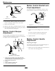
Figure30
1.31/4inches(8.3cm)4.3inches(7.6cm)
2.Backbladetip
5.Levelsurface
3.Frontbladetip
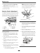
10.Loosenthewhizlocknutonthesideoftheyoke
andthejamnutontop.Finetunethescrew
adjusterbyturningittoget3inch(7.6mm)
height(seeFigure31).
Toincreasetheheight,turntheadjusterscrew
clockwise;todecrease,turncounterclockwise.
Figure31
1.Whizlocknut3.Jamnut
2.Adjusterscrew4.Yoke
11.Thebacktipsofthesidebladesshouldmeasure
31/4inches(8.3cm).Finetunerearadjusters
asrequired.
12.Re-measureuntilallfoursidesarethecorrect
height.Tightenallthenutsonthedeckliftarm
assemblies.
13.Lowerdischargedeector.
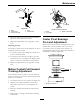
14.Ifthefourdecklinksdonothaveenough
adjustmenttoachieveaccuratecutheightwiththe
desiredrake,thesinglepointadjustmentcanbe
utilizedtogainmoreadjustment(seeFigure32).
Figure32
1.Singlepointheightadjustmentbolt
2.Frontheight-of-cutplatemountingbolt
3.Rearheight-of-cutplatemountingbolt
15.Toadjustthesinglepointsystem,rstloosenthe
frontandrearheight-of-cutplatemountingbolts.
41