LAZER Z ADVANTAGE SERIES X MODELS ® For Serial Nos. 850,000 & Higher Lazer Z (LZAS) Units Part No. 4500-563 Rev.
WARNING CALIFORNIA Proposition 65 Warning The engine exhaust from this product contains chemicals known to the State of California to cause cancer, birth defects, or other reproductive harm. Important: The engine in this product is not equipped with a spark arrester muffler. It is a violation of California Public Resource Code (CPRC) Section 4442 to use or operate this engine on any forest-covered, brush-covered, or grass-covered land as defined in CPRC 4126.
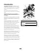
Introduction CONGRATULATIONS on the purchase of your Exmark Mower. This product has been carefully designed and manufactured to give you a maximum amount of dependability and years of trouble-free operation. This manual contains operating, maintenance, adjustment, and safety instructions for your Exmark mower. BEFORE OPERATING YOUR MOWER, CAREFULLY READ THIS MANUAL IN ITS ENTIRETY.
Contents Pump Drive Belt Tension............................... 42 Deck Belt Tension ........................................ 42 Adjusting the Parking Brake........................... 42 Electric Clutch Adjustment............................ 44 Motion Control Linkage Adjustment ............. 45 Motion Control Damper Adjustment............. 46 Motion Control Neutral Lock Pivot Adjustment ............................................... 46 Motion Control Handle Adjustment ..............
Safety Safety • Never let children or untrained people operate or service the equipment. Local regulations may restrict the age of the operator. Safety Alert Symbol • Only adults and mature teenagers should operate a mower, and even mature teenagers should have adult supervision. Be sure a teenager: This Safety Alert Symbol (Figure 2) is used both in this manual and on the machine to identify important safety messages which must be followed to avoid accidents. 1.
Safety DANGER DANGER In certain conditions gasoline is extremely flammable and vapors are explosive. A fire or explosion from gasoline can burn you, others, and cause property damage. In certain conditions during fueling, static electricity can be released causing a spark which can ignite gasoline vapors. A fire or explosion from gasoline can burn you and others and cause property damage. • Fill the fuel tank outdoors on level ground, in an open area, when the engine is cold.
Safety • Never operate the mower with damaged guards, shields, or covers. Always have safety shields, guards, switches and other devices in place and in proper working condition. • Never mow with the discharge deflector raised, removed or altered unless there is a grass collection system or mulch kit in place and working properly. • Do Not change the engine governor setting or overspeed the engine.
Safety • Be aware of the mower discharge path and direct discharge away from others. • Do Not operate the mower under the influence of alcohol or drugs. • Use extreme care when loading or unloading the machine into a trailer or truck. • Use care when approaching blind corners, shrubs, trees, or other objects that may obscure vision. Slope Operation Use Extreme caution when mowing and/or turning on slopes as loss of traction and/or tip-over could occur.
Safety • Disconnect battery or remove spark plug wire before making any repairs. Disconnect the negative terminal first and the positive last. Reconnect positive first and negative last. WARNING There is no rollover protection when the roll bar is down. Wheels dropping over edges, ditches, steep banks, or water can cause rollovers, which may result in serious injury, death or drowning. • Use care when checking blades. Wrap the blade(s) or wear gloves, and use caution when servicing them.
Safety CAUTION WARNING If the ignition is in the “ON” position there is potential for sparks and engagement of components. Sparks could cause an explosion or moving parts could accidentally engage causing personal injury. Hydraulic fluid escaping under pressure can penetrate skin and cause injury. Fluid accidentally injected into the skin must be surgically removed within a few hours by a doctor familiar with this form of injury or gangrene may result.
Safety Safety and Instructional Decals • Keep all safety signs legible. Remove all grease, dirt and debris from safety signs and instructional labels. • Replace all worn, damaged, or missing safety signs. • When replacement components are installed, be sure that current safety signs are affixed to the replaced components. • If an attachment or accessory has been installed, make sure current safety signs are visible.
Safety 109-3148 109-7232 1. Fast 2. Slow 3. Neutral 4.
Safety 116-0157 1. See Operator’s manual 116-0165 For Style B Slotted Nuts — See “Wheel Hub – Slotted Nut Torque Specification” in the Maintenance section 109-8483 1. Throttle–fast 2. Throttle–slow 3. Choke–on 4.
Safety 116-2643 For Style A Slotted Nuts — See “Wheel Hub – Slotted Nut Torque Specification” in the Maintenance section 117–2718 116-0752 1. Latch 2. Unlatch Message Display 1. 2. 3. 4. 5. 116-0906 For Kawasaki Liquid-Cooled Only Fuel Empty Half Full Battery 6. 7. 8. 9. 10. Hour meter PTO Parking brake Neutral Operator presence switch PTO Switch Symbols 116-1654 1. PTO–disengage 109-7069 14 2.
Specifications Specifications Model Numbers Serial Nos: 850,000 and Higher LZAS22KA484; LZAS22KA484CA; LZAS23KC524; LZAS25KC604; LZAS26LKA604; LZAS27KC524; LZAS27KC524CA; LZAS27KC604; LZAS27KC604CA; LZAS29KA724 Systems All units: – 25 amp main fuse – 25 amp charging system fuse – 10 amp PTO fuse – 15 amp accessory fuse Engine • Engine Specifications: See your Engine Owner’s Manual • RPM: Full Speed: 3750 ±50 RPM (PTO not engaged) Idle: 1500 ±100 RPM Safety Interlock System • LCD indicators appear for t
Specifications • • • • • • Hydrostatic Ground Drive System – Moving motion control levers outward (in slots) locks the drive system in neutral. PTO Engagement Switch: Engages electric clutch (to drive belt) which engages mower blades. Parking Brake Lever: Engages parking brake. Parking Brake Release Button: Releases parking brake. Deck Height Adjustment Lever: Sets cutting height to desired position. Deck Lift Pedal: Foot pedal that lifts deck.
Specifications Dimensions – 48 inch Deck: 16.25 inches (41.3 cm) – 52 inch Deck: 18.00 inches (45.7 cm) Overall Width: – 60 inch Deck: 20.50 inches (52.1 cm) 48 inch Deck 52 inch Deck Without Deck 45.7 inches (116.1 cm) 45.7 inches (116.1 cm) Deflector Up 51.8 inches (131.6 cm) 56.3 inches (143.0 cm) Deflector Down 59.6 inches (151.4 cm) 64.8 inches (164.6 cm) 60 inch Deck 72 inch Deck Without Deck 53.0 inches (134.6 cm) 59.1 inches (150.1 cm) Deflector Up 62.5 inches (158.8 cm) 73.
Specifications Accessory Weight Table Worksheet: Tread Width: (Center to Center of Tires, Widthwise) Use the table below to determine if extra weight is required for the unit. Identify the accessories and correct deck size and place the corresponding values in the Accessory Score column. If the Total Accessory Score meets the following, add the recommended weight kit. 48 inch Deck 52 inch Deck Drive Wheels 36.2 inches (91.9 cm) 38.5 inches (97.8 cm) Caster Wheels 32.8 inches (83.3 cm) 32.
Product Overview Product Overview *60 inch units which already have an under toe board mount weight as standard requires 116-1238 front toe board top mount kit instead of 116-1173.
Operation Operation The choke is used to aid in starting a cold engine. Moving the choke lever forward will put the choke in the “ON” position and moving the choke lever to the rear, to the detent, will put the choke in the “OFF” position. Do Not run a warm engine with choke in the “ON” position. Note: Determine the left and right sides of the machine from the normal operating position.
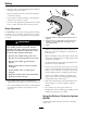
Operation The hour meter records the number of hours that the engine has run. Pull the lever up and rearward to engage the brake. Depress the release button and push downward to disengage the brake. Figure 7 1. Release button 2. Park brake The unit must be tied down and brake engaged when transporting. Figure 9 1. 2. 3. 4. 5. Ignition Switch Located on right console (see Figure 6). The ignition switch is used to start and stop the engine. The switch has three positions “OFF”, “ON” and “START”.
Operation Note: The handle must be horizontal and against the stop for operation. The fuel level is shown on a bar display. The indicator light appears when the fuel level is low (approximately one gallon remaining in the tank). Do Not tow machine. Drive Wheel Release Valves PTO Engagement Switch WARNING Located on right console (see Figure 6). Switch must be pulled out (up) to engage the blades. Switch is pushed in to disengage the blades.
Operation Figure 12 Figure 11 1. Green 2. Yellow 1. Latching position 2. Transport lock control 3. Red 4. Bar display 3. Non-latching position Pre-Start Warning Buzzer (Kawasaki Liquid-Cooled Only) Fill fuel tank on level ground. For best results use only clean, fresh regular grade unleaded gasoline with an octane rating of 87 or higher. Located on the side of the right hand console (see Figure 6). The buzzer is a warning signal that the engine is overheating. See the Troubleshooting section.
Operation 2. Apply forward pressure to the upper hoop of the roll bar. 3. Pull the knob and rotate 90° to hold in the unlatched position to lower the roll bar. 4. To return to the operate position, raise the roll bar, and then rotate knobs 90° so that the tabs interlock partially. Apply forward pressure to the roll bar upper hoop and observe that the knobs return to the completely latched position. Figure 14 1. Engaged 2. Partially engaged — Do Not operate with ROPS in this condition.
Operation Stopping the Engine attempts. Failure to follow these guidelines can burn out the starter motor. 1. Bring the unit to a full stop. 7. If the choke is in the “ON” position, gradually return choke to the “OFF” position as the engine warms up. 2. Move the motion control levers out to the neutral lock position. 3. Engage the parking brake. Engaging the PTO 4. Place the throttle midway between the “SLOW” and “FAST” positions. DANGER 5. Disengage the PTO.
Operation Driving in Reverse 1. Move the motion control levers inward to the neutral operate position. 2. To move rearward in a straight line, move both levers rearward with equal pressure. To turn right, release pressure on the RH motion control lever and the rear of the machine will move towards the rear and to the right. To turn left, release pressure on the LH motion control lever and the rear of the machine will move towards the rear and to the left. 3.
Operation Note: The foot operated deck lift assist lever can be used to momentarily lift the deck to clear objects. Be sure that PTO is disengaged. 5. Insert the height adjustment pin into the hole corresponding to the desired cutting height. See the decal on the side of the deck lift plate for cut heights. 8. Torque the 3/8–16 whizlock nut to 30-35 ft-lb (41-47 N-m) (Figure 19). 6. Push the deck lift pedal, release the transport lock and allow the deck to lower to the cutting height. 9.
Operation a surface for the frame members to contact if the unit starts to tip backward. If it is not possible to use one full width ramp, use enough individual ramps to simulate a full width continuous ramp. CAUTION This unit does not have proper turn signals, lights, reflective markings, or a slow moving vehicle emblem. Driving on a street or roadway without such equipment is dangerous and can lead to accidents causing personal injury.
Maintenance Maintenance Note: Determine the left and right sides of the machine from the normal operating position. WARNING WARNING While maintenance or adjustments are being made, someone could start the engine. Accidental starting of the engine could seriously injure you or other bystanders. The engine can become very hot. Touching a hot engine can cause severe burns. Allow the engine to cool completely before service or making repairs around the engine area.
Maintenance Maintenance Service Interval Every 500 hours Every 4,000 hours Maintenance Procedure • Replace the secondary air cleaner element (May need more often under severe conditions. See the Engine Owner’s Manual for additional information.) • Change the hydraulic filter and fluid. • Check the wheel hub slotted nut torque specifications. • Check the wheel lug nuts. • Check the park brake adjustment. • Change engine coolant.
Maintenance Voltage Reading Percent Charge Maximum Charger Settings 11.7–12.0 0–25% 14.4 volts/4 3 Hours amps 11.7 or less 0% 14.4 volts/2 6 Hours or More amps Charging Interval CAUTION Connecting the jumper cables incorrectly (wrong polarity) can immediately damage the electrical system. Be certain of battery terminal polarity and jumper cable polarity when hooking up batteries. Recommended Jump Starting Procedure Note: The following instructions are adapted from the SAE J1494 Rev. Dec.
Maintenance Figure 21 Figure 20 1. 2. 3. 4. 5. 6. 7. 1. Install bushing in blade prior to installing bushing in spindle. Positive (+) cable on discharged battery Positive (+) cable on booster battery Negative (–) cable on the booster battery Negative (–) cable on the engine block Booster battery Discharged battery Engine block B. Install bushing/blade assembly into spindle. Make sure the splines on the bushing are engaged in the spindle before tightening the bolt. 4.
Maintenance one second has elapsed if the handles are in. The delay will be 1/2 second if the handles are out. WARNING Incorrect installation of the blade or components used to retain the blade can be dangerous. Failure to use all original components and assembled as shown could allow a blade or blade component to be thrown out from under the deck resulting in serious personal injury or death.
Maintenance Check Seat Belt 1. Stop engine, wait for all moving parts to stop, and remove key. Engage parking brake. Service Interval: Before each use or daily 2. Drain oil while engine is warm from operation. Visually inspect seat belt for wear, cuts, and proper operation of retractor and buckle. Replace before operating if damaged. 3. The oil drain hose is located on right hand side of engine at the rear. Place pan under machine to catch oil. Remove plug from end of drain hose.
Maintenance Note: No adjustments are required for belt tension. Lubricate Grease Fittings Note: See chart for service intervals. 1. Stop engine, wait for all moving parts to stop, and remove key. Engage parking brake. 2. Lubricate fittings with one to two pumps of NGLI grade #2 multi-purpose gun grease. Refer to the following chart for fitting locations and lubrication schedule. Figure 24 1. Full 2.
Maintenance 13. Torque the nut to 75-80 in-lb (8-9 N-m), loosen, then re-torque to 20-25 in-lb (2-3 N-m). Make sure axle does not extend beyond either nut. 14. Reinstall the seal guards over the wheel hub and insert wheel into caster fork. Reinstall caster bolt and tighten nut fully. Important: To prevent seal and bearing damage, check the bearing adjustment often. Spin the caster tire. The tire should not spin freely (more than 1 or 2 revolutions) or have any side play.
Maintenance 9. Fill the hydraulic system as stated in Check Hydraulic Oil Level section. Replacement Filters Kohler Kohler P/N 24 050 13 Kawasaki (Air-Cooled & Liquid-Cooled) Kawasaki P/N 49019-7005 Exmark Premium Hydro Oil is recommended.
Maintenance Note: Do Not use anti-seize on wheel hub. WARNING • Style B (yellow zinc): Engine coolant is hot and pressurized and radiator and surrounding parts are hot. Spray or steam from hot, pressurized liquid in the engine cooling system and touching a hot radiator may cause severe burns. 1. Remove and discard the cotter pin. 2. Torque the slotted nut to 200 ft-lb (271 N-m). 3. Check distance from bottom of slot in nut to inside edge of hole. Two threads (0.1 inch) or less should be showing.
Maintenance the coolant level drops, add additional coolant to the radiator. 8. When the radiator is completely full and no additional coolant can be added, continue running and install the radiator cap. Make sure that the cap is completely seated by pressing down firmly while turning until the cap stops. Once the cap is installed, the engine may be stopped. Check Spark Arrester (if equipped) Figure 28 1. 2. 3. 4.
Maintenance Thread locking adhesives are required for some hardware on engines — see the Engine manual. Adjustments Copper-Based Anti-seize Note: Disengage PTO, shut off engine, wait for all moving parts to stop, engage parking brake, and remove key before servicing, cleaning, or making any adjustments to the unit. Copper-based anti-seize is used in the following location: CAUTION On threads of Blade Bolts. See Check Mower Blades section.
Maintenance 6. Insert the height adjustment pin into the 3 inch (7.6 cm) cutting height location. 7. Release the transport lock and allow the deck to lower to the cutting height. 8. Raise the discharge deflector. 9. Measure from the level surface to the front tip of the center blade. The measurement should read 3 inches (7.6 mm). Note: In most conditions, the back tips on the side blades should be adjusted 1/4 inch (6.4 mm) higher than the front. Figure 31 1. Whizlock nut 2. Adjuster screw 11.
Maintenance 16. If the deck is too low, tighten the single point adjustment bolt by rotating it clockwise. If the deck is too high, loosen the single point adjustment bolt by rotating it counterclockwise. CAUTION Raising the mower deck for service or maintenance relying solely on mechanical or hydraulic jacks could be dangerous. The mechanical or hydraulic jacks may not be enough support or may malfunction allowing the unit to fall, which could cause injury.
Maintenance 10. Remove all slack from cable by pulling on the caliper lever arm with a medium amount of force. Using hands and fingers only, push the caliper lever arm to engage the brake pads on the rotor until the lever stops. While holding the lever at the stopped position, use the other hand or fingers to pull the slack out of the cable threaded end through the swivel. Spin the standard nut against the swivel (see Figure 33).
Maintenance Note: Do Not remove the brake pole from the field shell/armature. The brake pole has worn to match the armature and needs to continue to match after the shim is removed to ensure proper brake torque. 18. Rotate the drive wheel release handle to the “operating” position. Refer to the Drive Wheel Release Valves section in Operation. 19. Install the rear tires and torque lug nuts to 90-95 ft-lb (122-129 N-m). 20. Remove jack stands.
Maintenance WARNING Engine must be running and drive wheels must be turning so motion control adjustment can be performed. Contact with moving parts or hot surfaces may cause personal injury. Keep fingers, hands, and clothing clear of rotating components and hot surfaces. Figure 38 1. Prior to starting the engine, push the deck lift pedal and remove the height of cut pin. Lower deck to the ground. 1. Feeler gauge • If the gap is less than 0.
Maintenance Motion Control Neutral Lock Pivot Adjustment The flanged nut can be adjusted to obtain a more desired motion control lever resistance (Figure 41). Figure 39 1. Double nuts 8. Shut off unit. Remove jumper wire from wire harness and plug connector into seat switch. 9. Remove the jack stands. 10. Raise the deck and re-install the height of cut pin. 11. Check that the machine does not creep in neutral with the park brakes disengaged. Figure 41 1. Flanged nut 2. Jam nut 1. Loosen the jam nut.
Maintenance Figure 43 RH Motion Control Shown Figure 42 1. Bolts 2. Control lever 3. Control arm shaft 4. Nuts 5. Slotted holes 3. Motion control lever 1. Screw 2. Cover plate 2. Move the control lever to the next set of holes. Secure the lever with the two bolts. Caster Pivot Bearings Pre-Load Adjustment 3. Repeat the adjustment for the opposite control lever.
Maintenance Cleaning Removing debris from the hydro fan cooling fins will allow the hydro system to run cooler and improve the life of the hydro system. Clean Engine and Exhaust System Area 1. Stop engine, wait for all moving parts to stop, and remove key. Engage parking brake. 2. Slide seat all the way forward. Service Interval: Before each use or daily (May be required more often in dry or dirty conditions.) 3. Remove accumulated debris from the hydro fan cooling fins.
Maintenance Waste Disposal Motor Oil Disposal Engine oil and hydraulic oil are both pollutants to the environment. Dispose of used oil at a certified recycling center or according to your state and local regulations. Battery Disposal DANGER Battery electrolyte contains sulfuric acid, which is poisonous and can cause severe burns. Swallowing electrolyte can be fatal or if it touches skin can cause severe burns.
Troubleshooting Troubleshooting Important: It is essential that all operator safety mechanisms be connected and in proper operating condition prior to mower use. When a problem occurs, do not overlook the simple causes. For example: starting problems could be caused by an empty fuel tank. The following table lists some of the common causes of trouble. Do not attempt to service or replace major items or any items that call for special timing of adjustment procedures (such as valves, governor, etc.).
Troubleshooting Problem Engine loses power Engine overheats. (Coolant temperature gauge is approaching the red zone or warning buzzer emits beep.) Possible Cause Corrective Action 1. Engine load is excessive 1. Reduce the ground speed. 2. Air cleaner is dirty. 3. Oil level in the crankcase is low. 4. Cooling fins and air passages for the engine are plugged. 5. Dirt in fuel filter. 6. Dirt, water, or stale fuel is in the fuel system. 2. Clean or replace the air cleaner element. 3.
Troubleshooting Problem Blades do not rotate. Possible Cause 1. Drive belt is worn, loose or broken. 1. Check the belt tension. 2. Deck belt is worn, loose or broken. 3. Deck belt is off pulley. 2. Install new deck belt. 3. Install belt on clutch and deck pulleys, idlers, and tensioning idler per routing decal on deck. 4. Replace the spring. 5. Refer to belt routing decal on deck. 4. Broken or missing idler spring. 5. Drive belt not routed correctly. Clutch will not engage. Corrective Action 1.
RECTIFIER START TERMINAL R TERMINAL S 53 NONE B+R+I+A B+R+I+S 2. RUN 3. START CIRCUIT "MAKE" TERMINAL S TERMINAL B TERMINAL R TERMINAL A 1. OFF POSITION IGNITION TERMINAL I TERMINAL I BATTERY TERMINAL B CONNECTIONS ACCESSORY TERMINAL TERMINAL A A B 2 1 2 1 2 1 2 1 1 2 1 2 B A PINK LT.
NONE B+R+I+A B+R+I+S 2. RUN 3. START CIRCUIT "MAKE" TERMINAL S TERMINAL B TERMINAL R TERMINAL A 1.
A BK BK - GND S B BU SW2 (PTO SWITCH) C FUEL SENDER PK + 2 BK BN BN 3 5 BN 8 F3 B PK 1 BN V 4 A PTO CLUTCH 4 10A BK BN 7 U2 TVS DIODE 5 SW5 BK 8 3 (NEUT_L) SW4 (NEUT_R) PTO PK ACCESSORIES FUEL GROUND PK 6 2 Y LTGR PK BRAKE 4 W 7 9 (BRAKE) SW6 GND 15A F4 HOUR METER 11 BK 8 10 T PK 7 1 12 OR B+ KEY_S GN (SEAT) SW7 BN PK OR GY R R OR PK 5 I SW1 (IGNITION) 2 B GN GY GY 1 S V 3 R PK 4 OPTIONAL NEUTRAL FUEL_SOLENOID SEAT
GN (+) (s) (P) S 3 BK 2 - 1 O 4 TEMP GAUGE PK OR PK OR ALARM 2 TONE + - BK BK A GND S B BU SW2 C FUEL SENDER PK + 2 PK 3 BN BN BK BN B BN V A PTO CLUTCH 4 PK 1 4 BK BN 7 U2 SW4 8 3 (NEUT_L) TVS DIODE BK 5 SW5 PTO (PTO SWITCH) F3 (NEUT_R) FUEL GROUND 5 8 10A 2 Y PK 6 11 F4 SW6 GND 15A W 7 9 (BRAKE) 4 8 HOUR METER LTGR BK SEAT PK NEUTRAL FUEL_SOLENOID BRAKE 10 T PK 12 1 OR SW7 GN (SEAT) BN PK OR GY R OR R 2 B 4 A V 3 R
Schematics Hydraulic Diagram 57
Exmark Lazer Z, Lazer Z Advantage Series X, and Vantage Turf Equipment 3 Year Limited Commercial Warranty 5 Year or 750 Hours Limited Consumer Warranty General Warranty Conditions and Products Covered Exmark Mfg. Co. Inc.
Notes: 59
Notes: 60
Service Record Date: Description of Work Done: 61 Service Done By:
G011841 Figure 45 This page may be copied for personal use. 1. The maximum slope you can safely operate the machine on is 15 degrees. Use the slope indicator to determine the degree of slope of hills before operating. Do Not operate this machine on a slope greater than 15 degrees. Fold along the appropriate line to match the recommended slope. 2. Align this edge with a vertical surface, a tree, building, fence pole, etc. 3. Example of how to compare slope with folded edge.
SEE EXMARK’S COMPLETE LINE OF ACCESSORIES AND OPTIONS MID-MOUNT RIDING ACCESSORIES AND OPTIONS CUSTOM RIDE SEAT SUSPENSION SYSTEM OPERATOR CONTROLLED DISCHARGE FULL SUSPENSION SEAT ROLL OVER PROTECTION SYSTEM (ROPS) DECK LIFT ASSIST KIT SUN SHADE HITCH KIT TRASH CONTAINER LIGHT KIT TURF STRIPER 12V POWER PORT ULTRA VAC COLLECTION SYSTEM MICRO-MULCH SYSTEM ULTRA VAC QUICK DISPOSAL SYSTEM OUT-FRONT RIDING ACCESSORIES AND OPTIONS CUSTOM RIDE SEAT SUSPENSION SYSTEM SNOW BLADE DUAL-TAIL WHEEL SN