
User guide


Sales • Service • Recycling 888.563.6300 in the USA 800.268.2698 in Canada
22
bl '0'
CON1
FS1
1234
bl
gy
bl
br
PCB1
bk
rd
bl
wh
wh '0'
wh '1'
bl '1'
wh '2'
bl '2'
Shunt
bl
gy
+
_
bl
FS2
16
wh '2'
wh '1'
bl '1'
wh '0'
rd
wh
bl
rd
rd
bk
CON 5
12345678
9101112131415
bl '2'
bl '0'
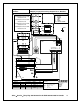
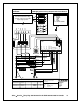
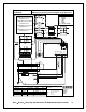
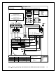
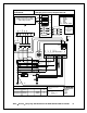
If any errors are apparent within this
diagram please inform CMP
engineering.
CMP Batteries Ltd,
Charger Division,
Unit 2 Pisces,
Mosley Road,
Trafford Park,
Manchester.
M17 1PF.
Component No:
CLT6006C
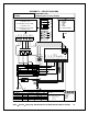
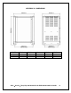
DRAWING TITLE:
GNB [UL] 3phase wiring diagram 600V Fuse/Breaker
KEY
bl BLUE
bk BLACK
br BROWN
gy GREY
rd RED
wh WHITE
YL/G YELLOW / GREEN
T1
DRAWING No: 4 - CMP - 2600 - 03 - WD - C
Drawn by:
Trev Peacock 01 10 03
Checked by:
MOD No: REV:
A--
YL/G
Materials: White Polypropylene 60u PP198 TC
Clear Overlaminate 60u PP20
Adhesive: AP51
Size: A5 (210mm x 147mm)
Text: As shown
Colour: Black on white
N
2
4
0
V
Transformer determines voltage
operation. Connect to T1 for 600V
input voltage operation.
br
F2
6
0
0
V
6
0
0
V
6
0
0
V
OR
L2
L1
L3
L1
L2
L3
L2
L1
L3
L2
L1
L3
Trev Peacock 19 12 03
-
C000068
B
Trev Peacock 17 03 04
-
C000045
C