® FLX200 SERIES INDUSTRIAL BATTERY CHARGERS INSTALLATION & OPERATING INSTRUCTIONS
TABLE OF CONTENTS TITLE 1. Important Operating Instructions 2. Introduction 3. Receiving Instructions 4. Location and Installation of Charger 5. Stacking 6. AC Electrical Supply 6.1 Branch Circuit Protection 6.2 AC Voltage Connections 6.3 Ground Connection 7. DC Output 8. Fault and Display Codes 9. Options 9.1 JIC Switch 9.2 Momentary Remote and Stop Operation 10. FLX200 Standard Charger Operation 11. Charger Functional Description 11.1 LED Descriptions 11.2 Display 11.3 Pause Push Button 11.
FLX200 SERIES INDUSTRIAL BATTERY CHARGERS 1. IMPORTANT OPERATING AND SAFETY INSTRUCTIONS SAVE THESE INSTRUCTIONS a) Before using the battery charger, read all the instructions in addition to the CAUTION, WARNING, and DANGER markings on the charger, battery, and all the associated equipment. b) Do not touch un-insulated parts of the DC output connector or the battery terminals, as there is a possibility of electric shock. c) Connect or disconnect the battery plug only when the charger output is off.
1. INTRODUCTION The GNB® FLX200 battery chargers are fan cooled, solid state, microprocessor controlled, SCR regulated chargers designed to make battery charging simple. They are factory set to charge flooded lead-acid batteries, but an upgrade can be purchased from a GNB Industrial Power service representative to enable the charger to service ELEMENT™ valve regulated lead-acid batteries.
inside, it is recommended you use a long handle hexagon key or screwdriver with the hexagon key inserted. This will allow you to go through the base plate to the bolts, which are located on the flange. b) Remove the bolts from the top cover of the base unit, but do not discard these, as they will be required to fix the two units together.
5. AC ELECTRICAL SUPPLY The charger must be connected to either a single phase or three phase, 60 Hertz (± 2%) AC power source. Three phase chargers cannot be powered with a single phase source.
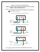
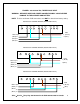
FIGURE 1: 120/208/240 VAC, SINGLE-PHASE INPUT WARNING: IMPROPER WIRE AND JUMPER CONNECTION MAY CAUSE SEVERE DAMAGE TO THE CHARGER AND BATTERY NOTE: Live connection ‘L’ Must be connected to the breaker. The mains input are the only user configurable connections. The blue and brown PCB connections must NOT be altered from factory setting.
FIGURE 2: 208/240/480 VAC, SINGLE-PHASE INPUT WARNING: IMPROPER WIRE AND JUMPER CONNECTION MAY CAUSE SEVERE DAMAGE TO THE CHARGER AND BATTERY NOTE: Live connection ‘L’ Must be connected to the breaker. The mains input are the only user configurable connections. The blue and brown PCB connections must NOT be altered from factory setting.
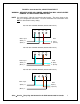
FIGURE 3: 208/240/480 VAC, THREE-PHASE INPUT WARNING: IMPROPER WIRE AND JUMPER CONNECTION MAY CAUSE SEVERE DAMAGE TO THE CHARGER AND BATTERY NOTE: The blue and brown PCB connections must NOT be altered from factory setting.
6.2 AC VOLTAGE CONNECTIONS To connect the input AC voltage, route the AC conduit through the knockout hole provided. Continue the AC wiring to the breaker terminals L1 (N) and L2 (L) (single phase input) or L1, L2, and L3 (three phase input). For proper connection, torque the screws to approximately 25 inch-pounds. 6.3 GROUND CONNECTION It is a requirement to ground the chassis while the charger is connected to AC power. The charger comes with a threaded M6 hole, clearly marked on the chassis.
6. DC OUTPUT The DC charging cable has a commonly used battery plug or receptacle. The polarity of the charger plug must be the same as the battery connector. The BLACK DC cable must be connected to the battery negative terminal (-) and the RED DC cable must be connected to the battery positive terminal (+). The charger will not operate in a reversed polarity condition. The DC output fuse is a "fast-acting" fuse used to protect the power semiconductors of a charger.
10.
11. CHARGER FUNCTIONAL DESCRIPTION 11.1 LED Descriptions LED Yellow Flashing Yellow Solid Green Flashing Green Solid Red Description High Rate Current 80% Charged Cool Down Charge Complete Fault – See page 16 for codes 11.2 DISPLAY The display by default shows the charging current during the charge cycle. The display may be changed to show voltage, time or Amp-Hours by pressing the FUNCTION button. The display may show additional messages as the charge cycle progresses or a fault occurs. 11.
11.5 AUTO BALANCE The charger maintains a current equal to 32% of the maximum output that is activated by voltage, on at 2.15VPC and off at 2.35VPC with a time limit of 2 hour if 2.35VPC is not reached. When current is flowing, amps will be displayed and the yellow LED will be illuminated. When no current is flowing, the display will show ‘StSt’. The FUNCTION button can select charge information. The green LED will remain illuminated. 11.6 EQUALIZE STAGE Equalize charge consists of 3.
If less than 3.0VPC, current will flow for 5 minutes and the charge will be suspended for 5 minutes. The cycle is repeated until the battery voltage is greater than 1.70 VPC at the end of the 5-minute rest period. If the battery voltage is greater than 1.70 VPC at the end of the 5-minute rest period, the battery recovery mode will cease and charge will start from stage 1 with smart start disabled. If 3.
During the 10-minute Refresh Charge period the display will toggle between ‘rEFr ’ and the output current. The yellow LED is illuminated and the green LED will remain illuminated and the FUNCTION button can select charge status. The charger will remain in the Refresh Charge stage until the battery is disconnected. 11.12 CHARGE TIME The amount of time a battery charges will vary depending on the depth of discharge (DOD). Once the battery has reached 80% charged, the cycle will be terminated after 3.
APPENDIX A – FAULT CODES CODE STATUS DESCRIPTION F01 N Over discharged battery (<1.90vpc after 30 seconds of charge) F02 N Deep discharged battery (<1.90vpc after 30 seconds of charge > 1.90vpc) F03 N Sulphated battery F04 S Charger over heating F05 S Mains failed during charge F06 R No output current F07 C Incorrect battery < 1.70 F07 (+Y led on) C Incorrect battery > 2.
APPENDIX B – FLX200 TROUBLESHOOTING SYMPTOM POSSIBLE CAUSE No Display No AC Power F01 F02 Deeply Discharged Battery Over Discharged Battery EXPLANATION / ACTION Check Input Power. Check Breaker. Mains fuse on Control Board Battery Voltage less than 1.9 volts per cell initially but rose above this level within the first minute. Check battery condition and Equalize. Battery less than 1.9 volts per cell after the first minute of charge.
APPENDIX C – SINGLE PHASE TECHNICAL DATA SINGLE PHASE MAXIMUM AC AMPS (RMS) SHIPPING DATA FLX or SCR Amp DC DC 120 208 240 480 600 Cabinet Model Numbers Hour Volts Amps VAC VAC VAC VAC VAC Size Lbs KG 200-06-260S1 200-06-475S1 200-06-600S1 200-06-865S1 200-06-965S1 200-09-475S1 200-09-600S1 200-09-865S1 200-09-965S1 200-12-260S1 200-12-475S1 200-12-600S1 200-12-750S1 200-12-865S1 200-12-965S1 200-18-260S1 200-18-475S1 200-18-600S1 200-18-750S1 200-18-865S1 200-24-260S1 200-24-475S1 2
APPENDIX D – THREE PHASE TECHNICAL DATA THREE PHASE MAXIMUM AC AMPS (RMS) SHIPPING DATA FLX or SCR Amp DC DC 120 208 240 480 600 Cabinet Model Numbers Hour Volts Amps VAC VAC VAC VAC VAC Size Lbs Kg 200-06-475T1 200-06-600T1 200-06-750T1 200-06-865T1 200-06-965T1 200-06-1050T1 200-06-1200T1 200-06-1450T1 200-12-475T1 200-12-600T1 200-12-750T1 200-12-865T1 200-12-965T1 200-12-1050T1 200-12-1200T1 200-12-1450T1 200-18-260T1 200-18-475T1 200-18-600T1 200-18-750T1 200-18-865T1 200-18-96
APPENDIX F – CIRCUIT DIAGRAMS Component No: CLT6006 DRAWING TITLE: GNB [UL] 3phase wiring diagram KEY For 208V input connect to 208V connections on T1 L1 L1 For 240V input connect to 240V connections on T1 L2 L2 L3 L3 For 480V input connect to 480V connections on T1 bl bk br gy rd wh YL/G BLUE BLACK BROWN GREY RED WHITE YELLOW / GREEN OR L1 L1 240V 480V 208V 480V 208V 240V 480V 240V N 208V YL/G L2 L2 L3 L3 bl br gy br bl bl T1 PCB1 CON1 4 3 2 1 13 12 11 10 9 8 7 6 5
Component No: CLT6005 DRAWING TITLE: GNB [UL] Single phase wiring diagram Fuse / Breakers KEY bl bk br gy rd wh YL/G N For 120V input connect to 120V connections on T1 For 208V input connect to 208V connections on T1 L BLUE BLACK BROWN GREY RED WHITE YELLOW / GREEN OR For 240V input connect to 240V connections on T1 N N For 480V input connect to 480V connections on T1 YL/G OR L L 240V 208V 120V 0V 240V 0V OR PCB1 br bl gy br bl bl CON1 4 3 2 1 240V 480V 208V 0V FS1 CON 5 T
Component No: CLT6006C DRAWING TITLE: GNB [UL] 3phase wiring diagram 600V Fuse/Breaker KEY L1 L1 Transformer determines voltage operation. Connect to T1 for 600V input voltage operation.
Component No: CLT6005JIC DRAWING TITLE: GNB [UL] Single phase wiring diagram single phase JIC KEY bl bk br gy rd wh YL/G N For 120V input connect to 120V connections on T1 For 208V input connect to 208V connections on T1 L OR For 240V input connect to 240V connections on T1 N For 480V input connect to 480V connections on T1 N N L L OR L 240V 208V 120V 0V 240V 0V BLUE BLACK BROWN GREY RED WHITE YELLOW / GREEN PCB1 br bl gy br bl bl OR CON1 4 3 2 1 240V 480V 208V 0V FS1 CON
Component No: CLT6006JIC DRAWING TITLE: GNB [UL] 3phase wiring diagram JIC KEY L1 L1 L2 L2 For 208V input connect to 208V connections on T1 NOTE ISOLATOR AND BREAKER MAY BE COMBINED bl bk br gy rd wh YL/G L3 L3 BLUE BLACK BROWN GREY RED WHITE YELLOW / GREEN OR For 240V input connect to 240V connections on T1 L1 L1 For 480V input connect to 480V connections on T1 L1 L2 L2 L2 L3 240V 480V 208V 480V 240V 208V 480V 240V N 208V L3 L3 YL/G br gy br bl bl T1 bl PCB1 CON1 4 3
Component No: CLT6006CJIC DRAWING TITLE: GNB [UL] 3phase wiring diagram 600V JIC KEY L1 L1 Transformer determines voltage operation. Connect to T1 for 600V input voltage operation.
APPENDIX G – DIMENSIONS CABINET Size M4 Size M5 Size M6 DIM. A 19.69” 23.62” 23.62” DIM. B 26.65” 26.65” 42.00” DIM. C 16.93” 20.87” 23.62” DIM. D 17.54” 21.48” 21.48” DIM. E 12.99” 16.93” 19.69” Sales • Service • Recycling 888.563.6300 in the USA 800.268.
® SALES – SERVICE - RECYCLING TOLL FREE 1-888-563-6300 in the USA 1-800-268-2698 in Canada GNB Industrial Power A Division of Exide Technologies U.S.A.- Tel: 888.563.6300 Canada - Tel: 800.268.2698 V19CIL5200ULF 2006-11 www.exide.