
User guide


INSTALLING THE AT30
4
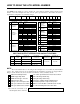
1.5. MOUNTING THE AT30
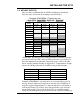
Chose the mounting method for the unit enclosure from the table below.
ENCLOSURE ENCLOSURE
MANUAL
SECTION
MOUNTING METHOD
Style-5018 Style-5030/163/198
1.5.1 Floor-Mounting STANDARD STANDARD
1.5.2 Wall-Mounting OPTIONAL n/a
19in / 483mm
Rack-Mounting
n/a n/a
1.5.3
23-24in / 584-610mm
Rack-Mounting
OPTIONAL n/a
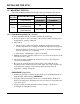
1.5.1. Floor-Mounting the AT30 (standard)
To floor mount the AT30, you must consider the following:
1. Overall footprint of enclosure. Refer to the standard outlines drawing listed
in Appendix C, starting on Page 66.
2. The location:
• Should be free of drips and splatter. If dripping liquids are a problem,
install a drip shield. See ordering information in Appendix B on page 65.
• Should be between 32 and 122 °F / 0 and 50 °C, with relative humidity
between 5 and 95% non-condensing.
• Must be free of flammable or explosive materials.
3. Maintain at least 6in / 152mm of free air on top, bottom and both sides of the
enclosure for air cooling.
4. Allow at least 36in / 914mm front clearance for access to the charger for
operation and maintenance.
5. Be conscious of future input and output wiring to the AT30. Note the
standard pre-fab conduit knockouts located on the sides (and sometimes top)
of the enclosure, featured on the standard outline drawings listed in
Appendix C, starting on Page 66.
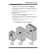
PROCEDURE (Style-5018)
1. Install four (4) 0.25in / 6.4mm bolts into the floor per mounting dimensions
featured in the outline drawing (JE5085-00).
2. Using the methods described in Section 1.4, carefully lift the AT30 above
the floor-mounting bolts. Guide the enclosure onto the floor bolt pattern and
lower it into place.
3. Add appropriate mounting hardware (0.25in / 6.4mm), onto the floor-
mounting bolts and tighten securely.