AT 30 SERIES CHARGERS I & O MANUALS SECTION 94.
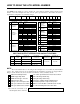
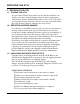
HOW TO READ THE AT30 MODEL NUMBER Your AT30 model number is coded to describe the options that are included. Please find the model number on the data nameplate and write it in the spaces provided below. Then follow the chart to determine the configuration of your battery charger.
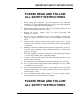
IMPORTANT SAFETY INSTRUCTIONS PLEASE READ AND FOLLOW ALL SAFETY INSTRUCTIONS 1. Before using this equipment, read all instructions and cautionary markings on: A) this equipment, B) battery, and C) any other equipment to be used in conjunction with this equipment. 2. This manual contains important safety and operating instructions, and therefore should be filed for easy access. 3. Remove all jewelry, watches, rings, etc. before proceeding with installation or service. 4.
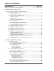
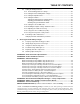
TABLE OF CONTENTS QUICK OPERATION .................................................................................................. Back Cover HOW TO READ THE AT30 MODEL NUMBER .............................................Inside Front Cover IMPORTANT SAFETY INSTRUCTIONS ......................................................................................i 1 Receiving and Installing the AT30 Battery Charger 1.1 Storing the AT30 ..............................................................................
TABLE OF CONTENTS 2.3 Setting the AT30 parameters 2.3.1 Understanding parameter settings .................................................................30 2.3.2 Setting the Float and Equalize voltages.........................................................31 2.3.3 Setting the Equalize timer ..............................................................................32 2.3.4 Setting the Alarms..........................................................................................
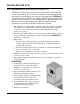
RECEIVING THE AT30 1. RECEIVING THE AT30 1.1. STORING THE AT30 If you store the AT30 for more than a few days before installation, you should store it in its original shipping container, and in a temperature controlled, dry climate. Ambient temperatures of 32 to 122° F / 0 to 50° C are acceptable. Storage should not exceed 2 years due to the limited shelf life of the dc filter capacitors when they are not in service. 1.2.
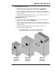
INSTALLING THE AT30 1.4. MOVING THE AT30 Once you have established that the AT30 is undamaged, identify the enclosure style of your unit by referring to the table below.
INSTALLING THE AT30 1.5. MOUNTING THE AT30 Chose the mounting method for the unit enclosure from the table below. ENCLOSURE ENCLOSURE MANUAL MOUNTING METHOD SECTION Style-5018 Style-5030/163/198 1.5.1 1.5.2 1.5.3 Floor-Mounting Wall-Mounting 19in / 483mm Rack-Mounting 23-24in / 584-610mm Rack-Mounting STANDARD OPTIONAL STANDARD n/a n/a n/a OPTIONAL n/a 1.5.1. Floor-Mounting the AT30 (standard) To floor mount the AT30, you must consider the following: 1. Overall footprint of enclosure.
INSTALLING THE AT30 PROCEDURE (Style-5030) 1. Install four (4) 0.375 / 9.5mm or 0.5in/12.7mm bolts into the floor per mounting dimensions featured in the outline drawing (JE5086-00). 2. Using the methods described in Section 1.4, carefully lift the AT30 above the floor-mounting bolts. Guide the enclosure onto the floor bolt pattern and lower it into place. 3. Add appropriate mounting hardware (0.375 / 9.5mm or 0.5in/12.7mm), onto the floor-mounting bolts and tighten securely. PROCEDURE (Style-163) 1.
INSTALLING THE AT30 1.5.2. Wall-Mounting the AT30 (Style-5018 enclosure only) AT30 battery chargers housed in the floor-mounted Style-5018 enclosure can be wall-mounted. You do not need to modify the standard Style-5018 enclosure for wall mounting, but a special wall-mounting kit (EI5008-00) is required. For kit availability see ordering information in Appendix B on page 65. The kit includes two (2) mounting brackets, hardware and special instructions for the wall mounting procedure.
INSTALLING THE AT30 Style-5018 Wall-Mounting NOTE 1. Refer to the outline drawing (JE5085-00) in Appendix C, on Page 66 for overall size, mounting dimensions and cabinet specifications for the Style5018 enclosure.
INSTALLING THE AT30 1.5.3. Rack-Mounting the AT30 (Style-5018 enclosure only) AT30 battery chargers housed in the floor-mounted Style-5018 enclosure can be installed in most relay racks with standard EIA hole spacing. You do not need to modify the standard Style-5018 enclosure for rack mounting, but a special rack-mounting kit (EI0193-03) is required. For kit availability see ordering information in Appendix B on page 65.
INSTALLING THE AT30 Style-5018 Rack-Mounting NOTES 1. Units are installed from the front. 2. Refer to the outline drawing (JE5085-00) in Appendix C, on Page 66 for overall size, mounting dimensions and cabinet specifications for the Style5018 enclosure.
INSTALLING THE AT30 1.6. CHANGING THE TRANSFORMER TAPS IMPORTANT: AT30 battery chargers are designed for a single ac input supply voltage. Note the ac voltage listing on the data nameplate, and tag attached to the ac circuit breaker. If your particular site ac supply voltage does not match your AT30 ac input requirements, you MUST change the ac input circuit breaker (and/or fuses), and input surge suppressors. In addition, you must replace or rewire the transformer as described below.
INSTALLING THE AT30 PROCEDURE 1. Verify that all voltages within the AT30 are de-energized and locked out. 2. See Section 3.5 for necessary steps to follow when accessing internal components within the AT30. 3. Change the jumpers on the transformer (T1) as shown in the table below. 4. Always use all three (3) jumpers. 5. Make sure all connections are tight. 6. Check your work before reenergizing the AT30. 7. For more information, see the schematics & wiring diagrams in Appendix C.
INSTALLING THE AT30 1.7. MAKING THE AC INPUT CONNECTIONS Follow these steps to connect ac power to the AT30: 1. Use a branch circuit breaker or fused disconnect switch, properly sized for the maximum ac input current of the AT30. This rating is listed on the lefthand side of the charger's data nameplate. This device should have lockout capability so that the ac input can be de-energized for charger maintenance. A time delay circuit breaker or slow-blow fuse is recommended. 2. 3. 4. 5.
INSTALLING THE AT30 MAKING THE AC INPUT CONNECTIONS - GRAPHICS Style-5018 I/O Terminal Board (TB1) Detail user-supplied ac input wiring user-supplied ac input wiring Style-5030 I/O Terminal Board (TB1) Detail user-supplied ac input wiring Style-163 I/O Terminal Board (TB1) Detail 13
INSTALLING THE AT30 1.8. MAKING THE DC OUTPUT CONNECTIONS Follow these steps to connect the battery to the AT30: 1. Size the dc wiring to minimize voltage drop. The acceptable wire size depends on your installation. As a guideline, the voltage drop should not exceed 1% of nominal output voltage at full current. 2. Size the dc output wiring per your battery manufacturer's specifications and local codes for the rating of the batteries and/or load. 3.
INSTALLING THE AT30 MAKING THE DC OUTPUT CONNECTIONS - GRAPHICS user-supplied dc output wiring Style-5018 I/O Terminal Board (TB1) Detail user-supplied dc output wiring Style-5030 I/O Terminal Board (TB1) Detail Style-163 I/O Terminal Board (TB1) Detail user-supplied dc output wiring 15
INSTALLING THE AT30 1.9. WIRING THE AT30 FOR REMOTE SENSING You can wire the AT30 to regulate the output voltage at the battery terminals, instead of at the charger output terminals. Remote sensing does the following: 1. Compensates for voltage drop in the dc wiring between the AT30 and the battery. 2. Directly monitors the battery or dc bus voltage. The front panel meter displays the actual voltage on the battery or dc bus.
INSTALLING THE AT30 6. Connect user-supplied external remote sense leads from the battery or dc bus to the remote sense terminals on the I/O panel. 7. Replace the two (2) dc output CU-AL compression lugs and tighten all hardware. 8. Check your work thoroughly. Replace the safety shield (if supplied) before reeneregizing the AT30. 9. Restart the AT30 according to the instructions in Section 2.1. NOTES 1. Use #16 AWG twisted pair. 2. Maximum current is 150 mA. 3. Run leads in their own conduit. 4.
INSTALLING THE AT30 1.10. WIRING TO THE REMOTE ALARM CONTACTS Built-in Summary (Common) Alarm Relay (standard) The Main Control PC Board (A1), mounted on the back of the front door, is equipped with one form C Summary Alarm contact (TB3) that transfers for any alarm. Follow the procedure below to wire an annunciator to this contact. See Section 2.2.7 for a description of the alarm functions. PROCEDURE 1. Allow 30in / 762mm of wire inside the enclosure (excess will be trimmed). 2.
INSTALLING THE AT30 Auxiliary Relay Board (optional) The optional Auxiliary Alarm Relay PC Board (A5), mounted on plastic stand-offs inside the enclosure, provides two (2) form-C contacts (TB4-1 through TB4-36) for each of the following individual alarms: • • • • • • High DC Voltage Low DC Voltage DC Output Failure AC Input Failure Ground Fault Detection (positive or negative) Summary (common) Alarm Alarm contacts (TB4) are as follows, shown in non-alarm condition: DC OUT DC OUT HVDC HVDC LVDC LVDC FAILU
INSTALLING THE AT30 1.11. INSTALLING THE TEMPCO PROBE ASSEMBLY (OPTIONAL) The temperature compensation probe contains a temperature-dependent resistor in an epoxy module that you install near your battery. There are three steps in installing the assembly: 1. Mounting the probe assembly near the battery. 2. Installing an interconnection cable from the probe assembly to the AT30. 3. Wiring the charger end of the cable to a terminal block on the main control circuit board.
INSTALLING THE AT30 • • Run the cable though a conduit if possible, but not through a conduit containing any power wiring. Route the other end to the probe at the battery and coil up excess cable. NOTE: If the standard (25ft / 7.6m) cable is not long enough, longer cable assemblies are available in lengths of 50, 100 & 200ft / 15.2, 30.5 & 61.0m. See Appendix B on page 65 for ordering information. • Be sure your wiring conforms to the NEC and your facility requirements. 5.
INSTALLING THE AT30 7. Check your work. Be sure that: • All connections are secure. • The shield is connected to ground at the charger end only (on the main circuit board). • The cable is connected to TB8 on the circuit board. Other terminal blocks may look similar. 8. Restart the AT30 using the startup procedure in Section 2.1. During startup, the AT30 displays LEAD on the front panel, indicating that the temperature compensation is set up for lead-acid batteries.
INSTALLING THE AT30 Note the following: • • • • • You should set the Float and Equalize voltages to the values recommended by your battery manufacturer for 77° F (25° C). When you enter the Edit mode to adjust the Float or Equalize voltage (see Section 2.3.2), the front panel meter shows the 77° F (25° C) value for the Float or Equalize voltage, even if the battery is warmer or cooler than 77° F (25° C).
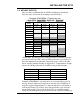
OPERATING THE AT30 2. OPERATING THE AT30 BATTERY CHARGER 2.1. STARTING THE AT30 2.1.1. Understanding the startup sequence The AT30 is set up at the factory to work with most common batteries and loads without further adjustment. When you start the AT30 for the first time, the factory settings (float voltage, equalize voltage, etc.) control the operation of the charger. You can change the settings after you start the charger. The FACTORY SETTINGS are shown in table on page 25.
OPERATING THE AT30 • • • If you have an optional temperature compensation probe installed, the front panel displays LEAD during startup, indicating that the temperature compensation is set up for lead-acid batteries. While this is being displayed, you can press any front panel key to change the display to read NICD, to change the temperature compensation setup for nickel cadmium batteries. The choice you make is saved internally, and will be used again by the AT30 then next time it starts.
OPERATING THE AT30 2.2. USING THE AT30 FRONT PANEL FEATURES 2.2.1. If the meter displays an error message When you apply power to the AT30 for the first time, the micro-processor control circuit performs a diagnostic check of the system. If it finds anything wrong, it writes an error code to the display, such as E 01. Below is a list of these error codes. See Section 3.2 on page 45 for a full explanation of each code.
OPERATING THE AT30 2.2.3. Selecting the Float or Equalize mode The AT30 has 2 output voltage settings, Float and Equalize. Use the Float mode for all normal battery charging and to operate your dc system. Use the Equalize mode if it is necessary to balance the level of charge among the cells of the battery. Consult your battery data sheets for information on equalize charging your battery. • Press the CHRG MODE key to change to the equalize mode.
OPERATING THE AT30 Manual Equalize Method Choose the manual equalize method when you want to equalize charge the battery, but only when you are able to monitor the battery voltage and gassing rate. After you select the manual equalize method, press the CHRG MODE key to put the charger into the equalize mode. The EQLZ indicator will light. Press the CHRG MODE key again to return the charger to the float mode. The FLOAT indicator will light.
OPERATING THE AT30 2.2.5. Testing the front panel indicators • Press the DOWN key. This is also the LAMP TEST key. The meter will display 8888, and all status & alarm indicators will light. The LAMP TEST key does not test the AC ON indicator. The AC ON indicator lights whenever ac power is present, and the ac circuit breaker is turned on. The LAMP TEST key does not operate when ac power is off.
OPERATING THE AT30 2.3. SETTING PARAMETERS IN THE AT30 2.3.1. Understanding Parameter Settings You can change the settings of the AT30 while the charger is operating, using the front panel controls. The changes you make take effect immediately, and are saved internally. If the charger is taken out of service, and then later returned to service, it restarts using the last values you set.
OPERATING THE AT30 2.3.2. Setting the Float and Equalize voltages • Press the EDIT/ENTER key. The FLOAT and DC VOLTS indicators light, and the display flashes the present value of the float voltage. Press and release the UP or DOWN key to increase or decrease the value in the display by one count, or press and hold the UP or DOWN key to scroll the value in the display upward or downward. When the display shows the float voltage you want to set, release the UP or DOWN key.
OPERATING THE AT30 2.3.3. Setting the Equalize Timer • Press the EDIT/ENTER key until the EQLZ HRS REMAINING, MANUAL TIMER and AUTO EQLZ TIMER indicators light, and the display flashes the present value of the equalize timer duration in hours. Press and release the UP or DOWN key to increase or decrease the value in the display by one count, or press and hold the UP or DOWN key to scroll the value in the display upward or downward.
OPERATING THE AT30 Setting the High DC Voltage Alarm • Press the EDIT/ENTER key until the HIGH DC VOLTAGE indicator flashes, and the display flashes the present value of the high dc voltage alarm. Press and release the UP or DOWN key to increase or decrease the value in the display by one count, or press and hold the UP or DOWN key to scroll the value in the display upward or downward. When the display shows the high dc voltage alarm point that you want to set, release the UP or DOWN key.
OPERATING THE AT30 Adjusting Ground Detection Sensitivity You can adjust the sensitivity of the ground detection alarm circuit. You must have a test resistor whose value is the sensitivity you want. You can adjust the sensitivity from 5 to 50 kΩ. The potentiometer for adjusting ground detection circuit sensitivity is located on the main control circuit board. It is the lower of the two potentiometers labeled RA3 SENS, as shown in the figure at the right.
OPERATING THE AT30 Using Ground Detection in Charger Standby Mode If you put the AT30 into standby mode by opening the dc circuit breaker (CB2), the ground detection circuit will send an erroneous negative ground alarm. There are two ways to work around this: • • Disable the ground detection circuit while the charger is in standby, as described below. Put the charger into standby by opening the ac input circuit breaker (CB1), and leaving the dc circuit breaker closed.
OPERATING THE AT30 2.3.6. Enabling the High DC Voltage shutdown feature The AT30 has a built-in high dc voltage shutdown feature. In case of any maladjustment or internal failure that results in a continuous output voltage that is too high, the AT30 shuts down after 30 seconds to protect the battery. The digital display shows E 03, and the summary alarm relay contact transfers. The AT30 is shipped with the high dc voltage shutdown feature disabled.
OPERATING THE AT30 2.3.7. Adjusting the Voltmeter Accuracy The AT30 voltmeter is adjusted at the factory to display the actual output voltage within ±0.25%. If you replace any component that affects meter accuracy, such as the main control PC board or R4, you should readjust the meter. This adjustment procedure is different from all others, because the meter reading remains constant, while the output voltage of the charger changes. Do this adjustment with a fully charged battery and with no load connected.
OPERATING THE AT30 2.3.8. Using the Low Level Detector (LLD) The AT30 battery charger is equipped with a summary alarm safety override circuit. This feature forces the summary alarm (common alarm) relay contact to transfer, sending an alarm, even if there is a catastrophic failure of the charger's control circuitry. A low battery voltage triggers the safety circuit. Main control board hardware, not software, maintains the low level detect circuit.
OPERATING THE AT30 2.3.9. Using the front panel security feature The AT30 charger is shipped with all the front instrument panel keys enabled. You can disable the following front panel functions: • Selecting Equalize method • Changing settings using the EDIT/ENTER key • Toggling the high dc voltage shutdown feature To disable the front instrument panel keys, open the AT30 door and locate the small plastic jumper J9 on the right side of the main control board. See the figure below.
OPERATING THE AT30 2.4. Performing routine maintenance WARNING High voltages appear at several points inside the AT30. Use extreme caution when working inside the unit. Do not attempt to work inside the AT30 unless you are a qualified technician or electrician. Disconnect and lock out all power from the AT30 before starting to remove or replace any components. Turn the ac power off at the distribution panel upstream from the charger. Disconnect the battery from the AT30 output terminals TB1(+/-). 2.4.1.
OPERATING THE AT30 2.4.4. Check temperature compensation probe (optional) If you are using the optional temperature compensation probe, be sure that the probe is securely installed. Be sure the connectors and the wiring from the probe to the AT30 charger are in good condition. If there is a failure of the temperature compensation probe, or the wiring, the AT30 charger displays the error code E 08. 2.4.5.
OPERATING THE AT30 SAMPLE PREVENTIVE MAINTENANCE PROCEDURE AT30 BATTERY CHARGER Suggested frequency: every 6 months Maintenance date Step Instructions (standard features) Clean battery charger • • Check all electrical connections and wiring • • • Check ac input voltage • Check dc output voltage • Check ripple voltage Test font panel indicators Test common alarm relay 42 Performed by • • • Results All vents clean and open. Remove dust and debris from inside of unit.
OPERATING THE AT30 Exercise front panel controls • • Switch from float to equalize, then back to float. Turn off the dc circuit breaker. E 07 may appear on display (requires at least 5% of rated output current). Reset breaker. Cycle through meter modes. • Cycle through equalize methods. • Turn off ac circuit breaker. The AC INPUT FAILURE indicator should light. Reset breaker. Use EDIT/ENTER key to scroll through settings. See page 30.
SERVICING THE AT30 3. SERVICING THE AT30 3.1. A STEP-BY-STEP TROUBLESHOOTING PROCEDURE The AT30 battery charger is fully tested and calibrated at the factory and should work for years with a minimum of attention. If you do encounter trouble, there are three steps you should take to find the problem and return the charger to service. 1. Check the front panel meter for an error code. The AT30 is able to diagnose common problems with the battery charger, or with the application or installation.
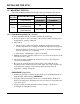
SERVICING THE AT30 3.2. INTERPRETING FRONT PANEL ERROR MESSAGES If the AT30 control circuit detects hardware or wiring problems, it may display an error code on the front panel. To solve an error code problem, refer to the table below, which lists the codes and procedures to use. WARNING High voltages appear at several points inside the AT30. Use extreme caution when working inside the unit. Do not attempt to work inside the AT30 unless you are a qualified technician or electrician.
SERVICING THE AT30 Error Code E 04 E 05 E 06 E 07 E 08 46 Meaning Repair Procedure Internal memory Any parameters that you set, such as Float or Equalize voltage, are saved internally. The internal memory is tested on startup. If the memory failure test fails, E 04 appears on the front panel display. The error may also appear if the controller was trying to write to the memory while a power failure occured. If an E 04 appears, try restarting the AT30 by turning the ac and dc breakers off, then on.
SERVICING THE AT30 Error Code E 08 E 09 Meaning Defective temperature compensation probe (continued) Misadjusted current limit E 10 Open internal feedback loop E 11 E 12 Not used E 13 E 14 A 01 A 02 Repair Procedure If the probe checks good, examine the wiring between the probe and the AT30. Also check the connection of the cable to the control circuit board on the back of the front panel. If the wiring is OK, then the probe needs to be replaced.
SERVICING THE AT30 3.3. USING THE TROUBLESHOOTING CHART WARNING High voltages appear at several points inside the AT30. Use extreme caution when working inside the unit. Do not attempt to work inside the AT30 unless you are a qualified technician or electrician. Disconnect and lock out all power from the AT30 before starting to remove or replace any components. Turn the ac power off at the distribution panel upstream from the charger. Disconnect the battery from the AT30 output terminals TB1(+/-).
SERVICING THE AT30 3.4. TROUBLESHOOTING CHART SYMPTOM Front panel meter displays all segments “On” or all segments “Off.” Charger may have no output. PROBABLE CAUSE 1. An external surge has interrupted operation of the microprocessor or the display controller. 1. Shorted AC breaker trips (or fuses rectifier diode or SCR clear) immediately RECOMMENDED ACTION 1A. Soft Reset of control board by pressing S7 reset switch.
SERVICING THE AT30 SYMPTOM DC breaker trips (or fuses clear) immediately PROBABLE CAUSE 1. Battery connected with reverse polarity 2. Defective rectifier bridge (if unfiltered AT30) 3. Defective Free-Wheeling diode CR4 4. Defective Polarity Diode CR1 (if filter assembly is installed) 5. Defective wiring DC breaker trips (or fuses clear) after a few minutes 50 1. Loose connection to breaker 2. Open SCR RECOMMENDED ACTION 1. Check and correct battery wiring if necessary. 2.
SERVICING THE AT30 SYMPTOM No output current, and AC ON lamp is out, but ac and dc breakers are on PROBABLE CAUSE 1. AC supply failure 2. Input fuse F1A/B/C blown 3. Defective wiring 4. Defective transformer T1 No output current, but AC ON lamp is on, and ac and dc breakers are on 1. Battery is fully charged 2. Float or Equalize voltage set too low 3. Wrong ac input voltage, or mistapped T1 4. Defective wiring RECOMMENDED ACTION 1.
SERVICING THE AT30 SYMPTOM Front panel is dead, but ac and dc voltages are present at TB1 PROBABLE CAUSE 1. Control boards are not connected 2. Defective Main Control board A1 3. Defective wiring 1. Defective Front panel dies during ac power resistor power failure R3 and dc voltage is present at TB1 2. Defective wiring Charger output voltage too high, not controllable 52 RECOMMENDED ACTION 1.
SERVICING THE AT30 SYMPTOM Output voltage does not agree with front panel meter PROBABLE CAUSE RECOMMENDED ACTION 1. Temperature compensation probe is installed 1. If the optional temperature compensation probe is installed, the output voltage may be different from the selected float or equalize voltage. The difference in the voltages depends on the probe temperature. The front panel meter always displays the selected voltage as if the battery were at 77° F / 25° C. 2. Circuit board, 2.
SERVICING THE AT30 SYMPTOM Input current too high PROBABLE CAUSE 1. Wrong ac input voltage, or T1 wired incorrectly 2. Defective rectifier bridge 3. Defective T1 Output ripple voltage too high RECOMMENDED ACTION 1. Be sure the T1 primary taps are wired correctly for your input voltage. See Changing Transformer Taps, Section 1.6. The actual ac input voltage must be at least 88% of the rated value for the AT30 to produce full output power. 2.
SERVICING THE AT30 PROBABLE CAUSE RECOMMENDED ACTION Lamp test key does not work, or some lamps do not light 1. No Vac 2. Control circuit board A1 is not secured to front panel 3. Defective Main Control board A1 1. The lamp test key does not work during an ac power failure. 2. Open the front panel, and be sure that the control circuit board is securely mounted on the standoffs on the back of the panel. All indicators should extend about 0.125in / 3.18mm through the front of the panel. 3.
SERVICING THE AT30 SYMPTOM LOW DC VOLTAGE indicator is on, but ac and dc breakers are closed; ac input voltage is normal; there is output current DC OUTPUT FAILURE indicator is on, but ac input voltage is normal, and ac & dc breakers are closed PROBABLE CAUSE 1. Battery is discharged 1. After an ac power failure, or a battery discharge for any other reason, it may take several hours to recharge the battery.
SERVICING THE AT30 SYMPTOM PROBABLE CAUSE RECOMMENDED ACTION AC INPUT 1. AC power FAILURE failure indicator is on 2. Upstream feed breaker/fuse is tripped 3. Defective wiring 4. Defective Main Control board A1 1. If the ac input power fails, the front panel AC ON indicator goes out, and the AC INPUT FAILURE indicator goes on. 2. Be sure the front panel ac circuit breaker (CB1) is closed. Measure the ac voltage at the AT30 input terminals (TB1-L1, TB1L2 and TB1-L3).
SERVICING THE AT30 3.5. REPLACING DEFECTIVE COMPONENTS WARNING High voltages appear at several points inside the AT30. Use extreme caution when working inside the unit. Do not attempt to work inside the AT30 unless you are a qualified technician or electrician. Disconnect and lock out all power from the AT30 before starting to remove or replace any components. Turn the ac power off at the distribution panel upstream from the charger. Disconnect the battery from the AT30 output terminals TB1(+/-).
SERVICING THE AT30 Replacing the Main Control (A1) and/or Gate Driver (A15) pc boards For details of this procedure, refer to service instruction (JD5012-00). CAUTION: Printed circuit boards A1 and A15 are sensitive to damage from static discharges. Leave replacement pc boards in their anti-static bags until you are ready to install them. Ground yourself before handling these boards by touching the ground stud on the back of the door. Handle these boards only by their edges.
SERVICING THE AT30 Replacing the ac surge suppressors (VR2, VR4 or VR5) Turn off and remove all power to the AT30. Remove the plexiglas safety shield. Disconnect the battery from the dc output terminals TB1(+/-). For VR2 (connected to L1), VR4 (connected to L2) or VR5 (connected to L3), remove the hardware from the input terminal Lx, and remove the lugged lead of the ac surge suppressor. Install one lead of the replacement surge suppressor onto the Lx terminal.
SERVICING THE AT30 Replacing the power (ballast) resistor (R3) - 48 and 130 Vdc units only For 48 Vdc and 130 Vdc AT30s, R3 is mounted with metal brackets onto the back panel of the enclosure. Cut wires # 49 and # 51 connected to R3 as close to the resistor leads as possible. Strip off 0.25in / 6.4mm of insulation from the cut ends of the wires. Unscrew the top mountingbracket and remove the existing resistor. Mount the new R3 and replace the top mounting-bracket. Polarity is not important.
SERVICING THE AT30 3.6. ORDERING REPLACEMENT PARTS All AT30 Series battery chargers ship with a supplemental parts data package, itemizing all components within the unit. Contact your sales representative to place an order for spare or replacement parts.
SERVICING THE AT30 Symbol Description Factory Part Number 12 Vdc 24 Vdc 48 Vdc 130 Vdc L1 Main Inductor see supplied Parts Data Package L2 Optional Filter Inductor see supplied Parts Data Package P5 Jumper for disabling Ground Detection circuit on Main Control PC Board (A1) RC0100-00 P7 Jumper for voltage selection on Auxiliary Relay PC Board (A5) RC0100-00 P9 Jumper for front panel lockout feature on Main Control PC Board (A1) RC0100-00 R1 Main DC Shunt (25 Adc) RB0008-13 R1 Main D
APPENDIX A SPECIFICATIONS Except as noted, all specifications apply at: 77°° F / 25 °C, nominal ac line voltage & nominal float voltage Specification Conditions 12 Vdc 24 Vdc 48 Vdc 130 Vdc Output voltage regulation Vac +10%, -12% 0 to 100% load Temp. 32-122° F / 0-50° C Freq. 60 ± 3 Hz 0.25% (see product literature for specific data) Transient response 20-100% load change, with battery connected Output voltage change ± 4% maximum Recovery to ± 2.0% in 200 ms Recovery to ± 0.
APPENDIX B FIELD INSTALLABLE ACCESSORIES AND OPTIONS All AT30 options/accessories listed below are available in kits for field installation, which contain all parts, mounting hardware and detailed installation instructions. Kit part numbers may be dependant upon enclosure type (e.g. Style-5018, Style-5030 & Style-163).
APPENDIX C (Standard Drawings) Outline: AT30 Battery Charger NEMA-1 Style-5018 Enclosure (JE5085-00) 66
APPENDIX C (Standard Drawings) Outline: AT30 Battery Charger NEMA-1 Style-5018 Enclosure (JE5085-00) http://www.ATSeries.net/PDFs/JE5085-00.
APPENDIX C (Standard Drawings) Outline: AT30 Battery Charger NEMA-1 Style-5030 Enclosure (JE5086-00) 68
APPENDIX C (Standard Drawings) Outline: AT30 Battery Charger NEMA-1 Style-5030 Enclosure (JE5086-00) http://www.ATSeries.net/PDFs/JE5086-00.
APPENDIX C (Standard Drawings) Outline: AT30 Battery Charger NEMA-1 Style-163 Enclosure (JE5095-00) 70
APPENDIX C (Standard Drawings) Outline: AT30 Battery Charger NEMA-1 Style-163 Enclosure (JE5095-00) http://www.ATSeries.net/PDFs/JE5095-00.
APPENDIX C (Standard Drawings) Internal Component Layout: AT30 Battery Charger Style-5018 Enclosure w/Common Options (JE5088-99) Note: This internal component layout drawing (JE5088-99) depicts an AT30 Series battery charger housed in a Style-5018 enclosure, with ALL available options. Standard components (A1 through VR7) are supplied in all such units. Optional components (A5 through VR3) are supplied only in those AT30 battery chargers configured with such options.
APPENDIX C (Standard Drawings) Internal Component Layout: AT30 Battery Charger Style-5018 Enclosure w/Common Options (JE5088-99) http://www.ATSeries.net/PDFs/JE5088-99.
APPENDIX C (Standard Drawings) Internal Component Layout: AT30 Battery Charger Style-5030 Enclosure w/Common Options (JE5089-99) Note: This internal component layout drawing (JE5089-99) depicts an AT30 Series battery charger housed in a Style-5030 enclosure, with ALL available options. Standard components (A1 through VR7) are supplied in all such units. Optional components (A5 through VR3) are supplied only in those AT30 battery chargers configured with such options.
APPENDIX C (Standard Drawings) Internal Component Layout: AT30 Battery Charger Style-5030 Enclosure w/Common Options (JE5089-99) http://www.ATSeries.net/PDFs/JE5089-99.
APPENDIX C (Standard Drawings) Internal Component Layout: AT30 Battery Charger Style-163 Enclosure w/Common Options (JE5098-99) Note: This internal component layout drawing (JE5098-99) depicts an AT30 Series battery charger housed in a Style-163 enclosure, with ALL available options. Standard components (A1 through VR7) are supplied in all such units. Optional components (A5 through VR3) are supplied only in those AT30 battery chargers configured with such options.
APPENDIX C (Standard Drawings) Internal Component Layout: AT30 Battery Charger Style-163 Enclosure w/Common Options (JE5098-99) http://www.ATSeries.net/PDFs/JE5098-99.
APPENDIX C (Standard Drawings) Instrument Panel / PC Board Detail: AT30 Battery Charger w/Optional Auxiliary Alarm Relay Board (JE5091-39) Note: This instrument panel drawing (JE5091-39) depicts the optional Auxiliary Alarm Relay PC Board (A5), which provides two (2) sets of individual form-c contacts (TB4) for all alarm conditions. Standard AT30 battery chargers feature one (1) set of form-c summary (common) alarm contacts (TB3).
APPENDIX C (Standard Drawings) Instrument Panel / PC Board Detail: AT30 Battery Charger w/Optional Auxiliary Alarm Relay Board (JE5091-39) http://www.ATSeries.net/PDFs/JE5091-39.
APPENDIX C (Standard Drawings) Schematic: AT30 Battery Charger Standard w/o Options (JE5092-00) 80
APPENDIX C (Standard Drawings) Schematic: AT30 Battery Charger Standard w/o Options (JE5092-00) http://www.ATSeries.net/PDFs/JE5092-00.
APPENDIX C (Standard Drawings) Schematic: AT30 Battery Charger w/Common Options (JE5092-99) 82
APPENDIX C (Standard Drawings) Schematic: AT30 Battery Charger w/Common Options (JE5092-99) http://www.ATSeries.net/PDFs/JE5092-99.
APPENDIX C (Standard Drawings) Connection Diagram: AT30 Battery Charger Mainframe Power Wiring w/Common Options (JE5093-99) Note: This connection diagram (JE5093-99) depicts the mainframe power wiring of an AT30 Series battery charger with ALL options available from the standard ordering code. Refer to the model number featured on the data nameplate and the supplied Parts Data Package report to identify, by circuit symbol, which components are applicable to each individual unit.
APPENDIX C (Standard Drawings) Connection Diagram: AT30 Battery Charger Mainframe Power Wiring w/Common Options (JE5093-99) http://www.ATSeries.net/PDFs/JE5093-99.
APPENDIX C (Standard Drawings) Connection Diagram: AT30 Battery Charger Control (Signal) Wiring (JE5094-00) 86
APPENDIX C (Standard Drawings) Connection Diagram: AT30 Battery Charger Control (Signal) Wiring (JE5094-00) http://www.ATSeries.net/PDFs/JE5094-00.
APPENDIX C (Standard Drawings) Connection Detail: AT30 Battery Charger I/O Panels & Rectifier Assemblies (JE5163-00) 88
APPENDIX C (Standard Drawings) Connection Detail: AT30 Battery Charger I/O Panels & Rectifier Assemblies (JE5163-00) http://www.ATSeries.net/PDFs/JE5163-00.
APPENDIX D RECOMMENDED FLOAT AND EQUALIZE VOLTAGES This table contains suggested values for commonly used batteries. Consult your battery manufacturer's documentation for specific values and settings for your battery type. Recommended Float Voltage/cell Recommended Equalize Voltage/cell Antimony (1.215 Sp. Gr.) Antimony (1.250 Sp. Gr.) Selenium (1.240 Sp. Gr.) Calcium (1.215 Sp. Gr.) Calcium (1.250 Sp. Gr.) Absorbed / Gelled Electrolyte * (sealed lead acid type) 2.17 2.20 2.23 2.25 2.29 2.33 2.33 2.
APPENDIX E COMMUNICATIONS MODULE Your AT30 Microprocessor-controlled Battery Charger has provisions for an optional Communications Module that allows the user to remotely monitor and control the unit over a serial connection. This option supports DNP3 Level 2 and Modbus protocols over RS-232 or RS-485 half-duplex. Industry-standard SCADA (Supervisory Control And Data Acquisition) systems will be able to control, monitor and log the events of the battery charger when this option is supplied.
APPENDIX F FORCED LOAD SHARING ONLINE SUPPLEMENT http://www.ATSeries.net/PDFs/JA5054-00.pdf INTRODUCTION Multiple battery chargers are sometimes employed in dc power systems to provide redundancy. Two or more chargers of the same voltage rating can be connected in parallel, each of them capable of powering the connected dc load and charging the battery.
APPENDIX F OPERATING CHARGERS WITH LOAD SHARING Restore external power connections to both AT30s, and restart according to the normal procedure in the AT Series Battery Charger Operating and Service Instructions. After the AT30s restart, the Primary charger attempts to establish communication with the Secondary.
MANUAL SPECIFICATIONS DOCUMENT NUMBER The text and graphics contained within this manual are controlled by the battery charger manufacturer's internal part number (JA5030-00). The revision level and dates of this manual's text and graphics are listed below. These controls supercede all other available dates. The first two and last two pages of this manual are reserved for company-specific front and back cover artwork.
MANUAL SPECIFICATIONS ONLINE AVAILABILITY An unlabeled version of this operating and service instruction manual is available online at http://www.ATSeries.net/PDFs/JA0102-03.pdf. Other related product operating manuals, feature and accessory special instructions, standard drawings (including the ones listed in this manual), field service instructions, and product application notes for the AT Series microprocessor-controlled battery chargers and battery charger products are available online at http://www.
GNB Industrial Power – The Industry Leader. ® ® Powered by GNB Industrial Power, a division of Exide Technologies, is a global leader in network power applications including communication/data networks, UPS systems for computers and control systems, electrical power generation and distribution systems, as well as a wide range of other industrial standby power applications.