
Instruction Manual
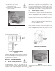
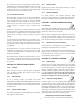
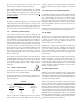

HANDLING AND STACKING HORIZONTAL MODULES
Figure 13
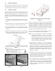
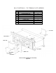
HARDWARE INSTALLATION SEQUENCE
Figure 14
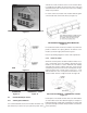
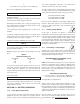
INSTALLING COMPLETED
HARDWARE HORIZONTAL STACK
Figure 15 Figure 16
8.3 Horizontal-Multiple Stacks
8.3.1 Stacking Base Modules
It is recommended that all of the first modules with bottom sup-
ports attached (see Section 8.1.1) be placed in position first. A
chalk line floor mark should be used to assure all stacks will be
in a straight line. This applies for stacks end-to-end or end-to-end
and back-to-back. Refer to Sections 6.5 and 8.1.3 for handling
and tip over procedures.
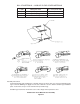
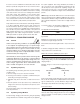
For stacks end-to-end, module ends should be butted together
so that module side channel ends meet (see Figure 17).
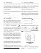
POSITIONING HORIZONTAL BASE MODULES
Figure 17
For stacks back-to-back, the two base modules are positioned to
provide a minimum 4.5” spacing between the bottoms of the
modules (not I-beam edges). Refer back to Figure 1.
Refer to layout/wiring diagram for seismic shim requirements.
8.3.2 Stack Tie Plates
At this time stack tie plates should be installed. It will be neces-
sary to temporarily remove the hardware fastening the base
modules to the I-beams. To achieve maximum stack stability,
especially where seismic conditions may exist, as well as prop-
er interfacing of inter-stack connections, metal tie plates are pro-
vided. The plates used on stacks end to end are 3” x 1” x 1/8”
with two 9/16” holes. Use one tie plate at each interface to con-
nect the module channels of adjacent stacks. See Figure 18.
TIE PLATE ASSEMBLIES - HORIZONTAL STACKS
Figure 18
Position plates on the module channels and secure with hardware
as shown. Where stacks have different heights (for example a 3
high stack adjacent to 4 high stack), install plates on shorter stack
top module and adjacent module. Torque hardware to 47 Newton-
meters (35 Ft-Lbs).
TOP MODULE
BASE MODULE
13