
Instruction Manual


10
S
ECTION 6: UNPACKING
PACKAGED MODULES
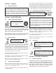
Figure 2
6.0 General
Do not remove shipping materials if a storage period is
planned, unless charging is required per Section 4.2.
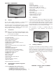
The battery modules are generally packed in groups. Lag bolts
retain the modules to the shipping pallet together with a pro-
tective hood bolted in place. Modules are also bolted together
at the top adjacent channels. See Figure 2.
6.1 Accessories
NOTE: Check accessory package against packing list to assure
completeness. Do not proceed with installation until all
accessory parts are available.
Accessories are packed separately and will include the following:
• Layout/wiring diagram
• Installation and operating instructions
• Lifting straps and lifting shackles
• Bottom Supports - I beams
• Hardware bag for I beam installation
• Hardware bag for module to module connections
• Standard clear covers
• Top clear covers
• Clear cover mounting brackets and assembly hardware
• Terminal plates
• Terminal plate mounting bracket
• Terminal plate hardware kit
• Terminal Plate Cover and assembly hardware
• Module tie plates and hardware (where required)
• Lead-Tin Plated copper connectors
• Hardware bag for connectors
• NO-OX-ID
®
“A” * grease
• Battery warning label
• Battery nameplate
• Cell numerals with polarity indicators
• Shims (leveling)
• Seismic Shims (where required)
• Alignment (drift) pins
*Registered Trademark of Sanchem Inc.
6.2 Recommended Installation Equipment
and Supplies
• Fork lift, portable boom crane or A-Frame hoist
— GX2000 Module Weight: 315 kg (695 lb)
— GX3000 Module Weight: 447 kg (985 lb)
—
GX2000 3-Cell Module Weight: 478 kg (1050 lb)
— Bottom Support (I-beams) Height: 10 mm (4 in)
• Chalk line
• Line Cord
• Torpedo level (Plastic)
• Plywood straight edge 1/2” x 4” x 48”
• Torque wrenches (100 in-lbs, 35 ft-lbs)
• Ratchet wrench with 10, 13, 17, 19 mm and
1/2 in. sockets
• Box wrenches 10, 13, 17, 19 mm sizes
• Vinyl electrical tape
• Paper wipers
• 3M Scotch Brite® scour-pads™*
• Hammer drill (Floor anchoring)
* Registered trademark of 3M
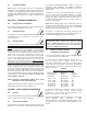
6.3 Unpacking
Carefully remove bolts and protective shipping hood. See Figure
3. Remove the bolts holding modules to shipping pallet. Also
remove hardware bolting upper channels of modules together.
Do not remove modules at this time. Base supports for horizon-
tally stacked modules are more easily attached before removing
modules from pallet (see Section 8 System Assembly).
Note: Placement of modules on shipping pallet has
no relationship to final installation and should be
disregarded.
UNPACKING MODULES
Figure 3
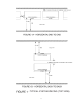
6.4 Handling of Modules
The design of the modular tray permits handling by a fork lift,
portable crane or by a hoist sling . Whichever method is used,
make sure equipment can safely handle the module weight. See
Section 6.2 for module weights. Always use the two lifting straps
and four lifting shackles for lifting and placement of modules.
See Figure 4.
HANDLING - LIFTING STRAP PLACEMENT
Figure 4