Installation and Operating Instructions For ABSOLYTE® GX Batteries SECTION 92.
TABLE OF CONTENTS SECTION 1: GENERAL ...................................................................................................................................6 SECTION 2: SAFETY MESSAGES .................................................................................................................6 2.0 Sulfuric Acid Electrolyte Burns ....................................................................................................6 2.1 Explosive Gases....................................
SECTION 7: 7.0 SECTION 8: SYSTEM ARRANGEMENTS ....................................................................................................11 Module Arrangements ...............................................................................................................11 SYSTEM ASSEMBLY ................................................................................................................11 8.0 Module Assembly Identification ..........................................................
SECTION 13: BATTERY OPERATION.............................................................................................................17 13.0 Cycle Method of Operation........................................................................................................17 13.1 Floating Charge Method ............................................................................................................17 13.2 Float Charge - Float Voltages......................................................
LIST OF ILLUSTRATIONS FIGURE DESCRIPTION 8 Fig. 1 Typical System Spacing 10 Fig. 2 Packaged Modules 10 Fig. 3 Unpacking Modules 10 Fig. 4 Handling - Lifting Strap Placement 11 Fig. 5 Handling - Module 11 Fig. 6 Typical System Arrangements 11 Fig. 7 I-Beam Hardware Installation 11 Fig. 8 I-Beam Support Installed 12 Fig. 9 Tip-Over Procedure - Shackle-Strap Usage 12 Fig. 10 Tip-Over Procedure - Photo 12 Fig. 11 Module After Tip-Over 12 Fig.
SECTION 1: GENERAL 1.0 Ensure that personnel understand the risk of working with batteries, and are prepared and equipped to take the necessary safety precautions. These installation and operating instructions should be understood and followed. Assure that you have the necessary equipment for the work, including insulated tools, rubber gloves, rubber aprons, safety goggles and face protection General Information CAUTION! 2.2.
3.1 Concealed Damage be provided to permit initial installation as well as for service or surveillance. After installation, any additional equipment installed after the battery should not compromise access to the battery system. Within 10 days of receipt, examine all cells for concealed damage. If damage is noted, immediately request an inspection by the carrier and file a concealed damage claim. Pay particular attention to packing material exhibiting damage or electrolyte staining.
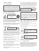
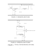
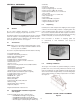
TYPICAL SYSTEM SPACING (TOP VIEW) 8
5.3 Temperature Variations DO NOT SELECT CABLE SIZE BASED ON CURRENT CARRYING CAPACITY ONLY. Cable size selection should provide no greater voltage drop between the battery system and operating equipment than necessary. Excess voltage drop will reduce the desired support time of the battery system. Sources of heat or cooling directed on portions of the battery can cause temperature variations within the strings resulting in cell voltage differences and eventual compromise of battery performance. 5.7.
SECTION 6: UNPACKING 6.0 • Chalk line • Line Cord • Torpedo level (Plastic) • Plywood straight edge 1/2” x 4” x 48” • Torque wrenches (100 in-lbs, 35 ft-lbs) • Ratchet wrench with 10, 13, 17, 19 mm and 1/2 in. sockets • Box wrenches 10, 13, 17, 19 mm sizes • Vinyl electrical tape • Paper wipers • 3M Scotch Brite® scour-pads™* • Hammer drill (Floor anchoring) * Registered trademark of 3M PACKAGED MODULES Figure 2 6.3 General Carefully remove bolts and protective shipping hood. See Figure 3.
shipment for completeness before continuing further. The Absolyte GX has a standard module configuration of two cells per module. Where application voltage requires, a module may have only one cell in a two-cell tray. For example, a 46 volt system will consist of eleven full modules and one single-cell module. Assemblies can be rotated 180° for proper polarity location. NOTE (for Figure 4): 1) Straps must be criss-crossed. 2) Observe lifting shackle orientation and proper channel hole use.
8.2 Handling of Modules The module/I-beam assembly may now be removed from the pallet using methods outlined in Section 6.5. See Figures 4 and 5. Remaining modules may be removed in a similar manner. 8.3 Tip Over Procedure In order to stack modules in the horizontal position, refer to Figures 9 through 11 to perform the tip-over procedure. The module/I-Beam assembly tip-over should be performed first.
chalk line floor mark should be used to assure all stacks will be in a straight line. This applies for stacks end-to-end or end-to-end and back-to-back. Refer to Sections 6.5 and 8.1.3 for handling and tip over procedures. For stacks end-to-end, module ends should be butted together so that module side channel ends meet (see Figure 17).
8.3.3 Horizontal Stacking 9.2 When all base modules are set in place, continue with stacking of subsequent modules. Procedures for assembly of multiple horizontal stacks are the same as outlined in section 8.1.3. Also consult layout/wiring diagram. Each stack should be built up in sequence to the same level until the top modules in all stacks are the last to be installed. The use of a line chord attached to upper module corners of opposite end modules as stacking progresses aids in alignment.
10.3 Also measure the total open circuit voltage from terminal plate to terminal plate. This should be approximately equal to 2.14 volts times the number of cells in the system, e.g., a 24 cell system would read: 24 x 2.14v = 51.4 volts. An incorrect voltage reading may mean connectors were installed incorrectly. Apply pressure sensitive warning label provided on a prominently visible module side or end. 10.4 9.6 Connection Resistance SECTION 11: PROTECTIVE MODULE COVERS 11.
BILL OF MATERIALS — TOP TERMINAL PLATE ASSEMBLY ITEM DESCRIPTION 1 PLATE, TOP TERMINAL 2 BRACKET, TERMINAL SUPPORT 3 LOCK WASHER, M10 4 FLAT WASHER, M10 5 NUT, M10 X .8D 6 BOLT, M10 X 40 7 COVER, FRONT 8 COVER, BACK 9 NUT, M6 X .
cells require approximately 105-110% of the ampere-hours removed to be returned to a full state of charge. or V corrected = V77°F - ((T actual - 77°F) x .003V/°F)) The upper voltage settings recommended, given that the maxium charge current is 5% of the nominal C100 Amp-hour rating and the ambient temperature is 25°C (77°F), are as follows: Please refer to Appendix A for standard values. STEP 1 2.28 ± 0.02 VPC @ 0-2% DOD 2.33 ± 0.02 VPC @ 3-5% DOD 2.38 ± 0.02 VPC @ >5% DOD 1.
BILL OF MATERIALS — MODULE CLEAR COVER MATERIALS ITEM 1 2 3 DESCRIPTION Cover Standoff Leg Standoff Key QTY PER SYSTEM 1 4 4 Assembly Instructions: Install standoff legs and standoff keys to module channel as shown. The cover is then installed by grasping it so that the GNB logo is upright. Locate slots at bottom of cover to bottom standoff legs and slide in place. Locate holes at top of cover and install to top standoff legs.
obtain the optimum service life from the battery, it is important to make sure the battery’s float voltage is within the recommended range. Do not use float voltages higher or lower than those recommended. Reduced capacity or battery life will result. 13.6 Float Current and Thermal Management Check and record battery terminal voltage on a regular basis. Monthly checks are recommended. See Section 15.0, Records.
the system equipment. This voltage, divided by the number of cells connected in series, will establish the maxi-mum volts per cell that may be used to perform the equalizing charge in the shortest period of time (not to exceed 2.35 VPC applicable at 77°F, 25°C). Refer to Table E for voltages and recommended time periods. It is best for users to establish their own baseline values for their battery as specifically configured. Do not rely on reference values.
SECTION 15: RECORDKEEPING SECTION 17: TEMPORARY NON-USE A pilot cell is selected in the series string to reflect the general condition of cells in the battery. The cell selected should be the lowest cell voltage in the series string following the initial charge. See Section 12.0 - Initial Charge. Reading and recording pilot cell voltage monthly serves as an indicator of battery condition between scheduled overall individual cell readings.
All terminal and intercell connections should be retorqued at least once every year to 11.3 Newton-meters (100 inch pounds). NOTE: Design and/or specifications subject to change without notice. If questions arise, contact your local sales representative for clarification. SECTION 20: CAPACITY TESTING 20.0 Capacity Testing When a capacity discharge test is desired, it is recommended that it be performed in accordance with IEEE-1188*, latest revision. An equalizing charge, as described in Section 14.
Volts TYPE: Conn. Ohmic Resist. C / R / I Temp ADDITIONAL COMMENTS: 1 2 3 4 5 6 7 8 9 10 11 12 13 14 15 16 17 18 19 20 21 22 23 24 25 26 27 28 29 30 No. Cell SYSTEM VOLTAGE: No. of CELLS: ADDRESS: COMPANY: DATE: Figure 22.1 31 32 33 34 35 36 37 38 39 40 41 42 43 44 45 46 47 48 49 50 51 52 53 54 55 56 57 58 59 60 No. Cell Volts TEMPERATURE: 61 62 63 64 65 66 67 68 69 70 71 72 73 74 75 76 77 78 79 80 81 82 83 84 85 86 87 88 89 90 No.
Figure 22.2 24 Volts TYPE: Conn. Ohmic Resist. C / R / I Temp ADDITIONAL COMMENTS: 121 122 123 124 125 126 127 128 129 130 131 132 133 134 135 136 137 138 139 140 141 142 143 144 145 146 147 148 149 150 No. Cell SYSTEM VOLTAGE: No. of CELLS: ADDRESS: COMPANY: DATE: 151 152 153 154 155 156 157 158 159 160 161 162 163 164 165 166 167 168 169 170 171 172 173 174 175 176 177 178 179 180 No.
APPENDIX A Temperature Corrected Float Voltages 3 4 5 6 7 8 9 10 11 12 13 14 15 16 17 18 19 20 21 22 23 24 25 26 27 28 29 30 31 32 33 34 35 36 37 38 39 2.23 2.35 2.35 2.34 2.34 2.33 2.33 2.32 2.32 2.31 2.31 2.30 2.30 2.29 2.28 2.28 2.27 2.27 2.26 2.26 2.25 2.25 2.24 2.23 2.23 2.22 2.22 2.21 2.21 2.20 2.20 Float Voltage at 25°C 2.24 2.25 2.26 2.35 2.35 2.35 2.34 2.34 2.33 2.33 2.32 2.32 2.31 2.31 2.30 2.29 2.29 2.28 2.28 2.27 2.27 2.26 2.26 2.25 2.24 2.24 2.23 2.23 2.22 2.22 2.21 2.21 2.20 2.20 2.35 2.
APPENDIX B MAXIMUM STORAGE INTERVAL BETWEEN FRESHENING CHARGES VERSUS AVERAGE STORAGE TEMPERATURE Maximum Storage Interval Months Days 25 6 0 77 6 0 26 5 18 78 5 23 27 5 7 79 5 17 28 4 26 80 5 10 29 4 16 81 5 4 30 4 7 82 4 29 31 3 29 83 4 23 32 3 21 84 4 18 33 3 13 85 4 12 34 3 7 86 4 7 35 3 0 87 4 3 36 2 24 88 3 28 37 2 18 89 3 23 38 2 13 90 3 19 39 2 8 91 3 15 40 2 4 92 3 11 41 1 29 93 3 7 42 1 25 94
APPENDIX C BONDING & GROUNDING OF BATTERY RACK INTRODUCTION 1. To insure personnel safety, and equipment protection, operation, and reliability, the battery rack should be connected to the Common Bonding Network (CBN). 2. Electrical continuity between modules is provided through the use of serrated hardware. Testing has shown that standard systems are compliant with the GR-1089-CORE, Issue 4, Section 9 requirements of the Bonding and Grounding tests. GROUNDING KIT INSTALLATION (OPTIONAL) 1.
GNB Industrial Power – The Industry Leader. ® GNB Industrial Power, a division of Exide Technologies, is a global leader in network power applications including communication/data networks, UPS systems for computers and control systems, electrical power generation and distribution systems, as well as a wide range of other industrial standby power applications.