EF – SERIES Installation and Operation Manual Ferro-Resonant Charger Sales – Service – Recycling Toll Free: U.S.A.
1
INDEX Page Section Description 3 - Safety Instructions 4 1.0 Installation 4 1.1 Receiving 4 1.2 Location 4 1.3 Line Voltage Adjustments 6 1.4 AC Service Requirements 6 1.5 Connecting AC Service to Charger 7 1.6 Grounding the Charger 7 1.7 Battery Connector and Charger Cable 7 1.8 Charging Rate Adjustment 8 2.0 Operation 8 2.1 046-0371 Control 14 2.2 046-0372 Control 26 3.0 Optional Features 26 4.0 Troubleshooting & Maintenance 28 5.0 Replaceable Parts 28 5.
SAFETY INSTRUCTIONS WARNING THIS EQUIPMENT CONTAINS LETHAL VOLTAGE LEVELS. INSTALLATION AND SERVICING MUST BE PERFORMED BY QUALIFIED PERSONNEL IMPORTANT: SAVE THESE INSTRUCTIONS! READ AND FOLLOW ALL INSTRUCTIONS BEFORE INSTALLING, OPERATING, OR SERVICING CHARGER. ANY DEVIATION CAN CAUSE SERIOUS AND PERMANENT DAMAGE. FAILURE TO FOLLOW THE INSTRUCTIONS VOIDS THE WARRANTY. 1. Install and ground the charger in accordance with the National Electric Code and your local electric code.
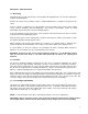
SECTION 1 - INSTALLATION 1.1. Receiving Immediately upon receipt of the charger, check it against the shipping invoice to ensure the shipment is complete and undamaged. Examine the outside of the packing for signs of rough handling before accepting the charger from the carrier. If there is evidence of damage, the receipt should be signed, and both copies (carrier's and receiving copies) marked "Shipment Received Damaged".
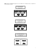
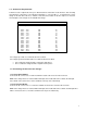
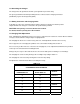
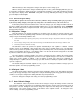
NOTE: When a 120/208/240 AC input unit is set for 120VAC a fuse neutral (brass tube) is required in the Line 2 (neutral) fuse position. Fig. 1.3.1. A.C. Voltage Adjustments 1 Ø 60Hz. (120/208/240) “A” Voltage Code Fig. 1.3.2. A.C. Voltage Adjustments 1Ø & 3Ø 60Hz. (208/240/480) “B” Voltage Code Fig.1.3.3. A.C. Voltage Adjustments 3 Ø 60Hz.
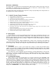
1.4. AC Service Requirements Follow local code requirements if they are different than the instructions in this manual. After checking the transformer connections as described in Paragraph 1.3, refer to Table 1-1, to determine the correct ratings for the AC cable, AC fuses, and AC service disconnect switch for the line amperes as listed on the nameplate of the charger for the available AC voltage TABLE 1-1 Line Amperes 000.0 003.0 005.0 008.0 011.5 016.0 018.5 022.5 027.5 032.5 040.5 048.5 065.0 081.0 096.
1.6 Grounding the Charger The charger must be grounded to the AC system ground for personnel safety. The green ground wire in the AC input wiring must be connected to the charger ground stud (identified by a green dot and ground symbol). 1.7 Battery Connector and Charging Cable Verify that the connectors on both the battery and the charger are attached so that the positive output terminal of the charger is connected to the positive battery terminal.
SECTION 2 - OPERATION The charger utilizes a standard ferro-resonant transformer, which provides isolation from the AC service line and regulates the charging current. The transformer output is connected to a full-wave bridge of silicon diodes, which provides DC charging current to the battery. The starting charge amps and length of time required for a charge vary depending on the charger model. See the data plate on the charger for information. 2.1.
When the battery is 80% charged, the charger starts phase 2 of the charge cycle. When a charge is finished, the charger automatically turns off. The yellow ‘Charging’ indicator goes out. If cool down is enabled, the display shows the cool down time remaining. If cool down is disabled or the time has elapsed, the display shows ‘0A x.xxVC ’ along with a message indicating the battery is ready and the green ‘Complete’ indicator lights. 2.1.4.1 Disconnecting the Battery Warning: Risk of explosion.
2.1.8 Viewing Charge Information Additional charge information is available any time by pressing the INFO button. This information is retained after the battery is disconnected until the next battery is connected. After 20 seconds the display returns to the default display of amps and volts per cell.
2.1.9 Charge Indications The following indications are not necessarily a result of a charger problem. They are typically caused by external problems such as AC line, poor battery conditions, connections, etc. If abnormal charge conditions are detected, the charge is terminated, the red fault LED lights and the display shows: DISPLAY F0 SHORTED CELL #.##VC ##:##HM DESCRIPTION Battery voltage did not reach 2.00 V/C within 30 minutes. #.
Note: F3 and F4 clear automatically if the battery voltage falls within acceptable limits. All indications except F8, F9 and F10 can be cleared by disconnecting the battery. For F8, F9 and F10, correct the condition that caused the indication and disconnect the battery to clear the indication. CAUTION: If F8 is showing, and the charger is providing current to the battery, remove AC power from the charger before disconnecting the battery. 2.1.10 F3 (Low Battery) Override If battery voltage is below 1.
2.1.12 Programming To enter programming mode, press and hold the EDIT button and while holding it, press the INFO button. The display shows a message describing the current parameter followed by the parameter‘s value.
SECTION 2 – OPERATION (continued) 2.2 046-0372 2.2.1 DESCRIPT CONTROL ION The 046-0372 charger control provides fully automatic battery charging in standard taper ferro-resonant chargers. The control is powered from a 24VAC transformer that provides isolation from the AC service line. The presence of a battery is detected by the control and causes a charge cycle to begin automatically.
046-0372 Setup Press SET, then 5, then START. The display shows ‘CHARGE ALGORITHM’ followed by ‘AL:’ and the algorithm number. Enter the algorithm number using the numeric keys on the keypad and press ENTER to save it. 2.2.2.4 Setting the Amp-Hour Rating Press SET, then 0. The display shows ‘BATTERY AH SIZE’ followed by ‘BS:’ and the battery size in amphours. Enter the amp-hour rating using the numeric keys on the keypad and press ENTER to save it. 2.2.2.
046-0372 Setup the desired setting (0: count down, 1: count up) and press ENTER to save it. If the direction is set to count down, the battery ready light does not come on until the cool down time has elapsed. If the direction is set to count up, the battery ready light comes on when the charge is complete and the elapsed time since the charge completed is displayed. 2.2.3.6 Setting Automatic Refresh To set the automatic refresh interval, press SET, then 5, then 8.
Table 1. Programmable Parameter List First Key SET SET SET SET Second Key SET 1 (AMPS) 2 (VOLTS) 3 (AH) Third Key none None None None SET SET 5 5 = 0 (TEST) SET SET SET SET 5 6 (I.D.) CLOCK 7 (TEMP) STOP None none none SET SET 8 (% RET.
Table 2.
10 Any Controlled Ferro HF Shop Charger 11 Geltec/Crown gel Controlled Ferro HF Special 12 Flooded Lead-Acid Controlled Ferro HF AGV Trickle Charge 13 Douglas VRLA Controlled Ferro HF Special 14 n/a Any Factory Test 15 Flooded Lead-Acid Controlled Ferro HF Opportunity Charge 16 Flooded Lead-Acid Ferro-Resonant Opportunity Charge 17 Exide Element Controlled Ferro HF Special 18 Lithium Controlled Ferro HF Special Phase 1: Constant current at the start rate until the float v
2.2.6 OPERA TION If alert messages are turned on, periodically a message shows for about 2 seconds in the display. With no battery connected, the control displays ‘0A 0.00VC’, and a ‘FERRO MAGNETICS’ alert is shown. When a battery is connected, a lamp test is performed. The charge begins, the yellow CHARGING indicator lights and the display shows ‘CHARGE PHASE 1’ periodically along with the charging amps and battery v/c.
2.2.7.3 TOBI® PI OPERATION The control has the ability to communicate with a Tobi® PI battery module. In order for communication to occur, it has to be enabled in the control. This is accomplished by setting the ‘BC’ parameter (see table 1). Setting the BC parameter to 0 disables communication. Setting the BC parameter to 1 enables normal communication.
2.2.7.4 CHARGE INDICATIONS The following indications are not necessarily a result of a charger problem. They are typically caused by external problems such as AC line, poor battery conditions, connections, etc. If abnormal charge conditions are detected, the charge is terminated, the red FAULT indicator lights and the display shows the code: DISPLAY F0 SHORTED CELL #.##VC ##:##HM F1 SHORTED CELL #.##VC ##:##HM F2 HOT BATTERY ###°F #.##VC F3 LOW VOLTS ###A #.##VC F4 HIGH VOLTS ###A #.
Note: F3 and F4 clear automatically if the battery voltage falls within acceptable limits. All indications except F8, F9 and F10 can be cleared by disconnecting the battery. For F8, F9 and F10, correct the condition that caused the indication and disconnect the battery to clear the indication. CAUTION: If F8 indication is showing, and the charger is providing current to the battery, remove AC power from the charger before disconnecting the battery. 2.2.7.
2.2.8.9 Display Charger Identification Number Chargers that are part of an I’m Cool Battery Selection System or a TOBi® Battery Management System have a unique identifying number. To view this ID number, press I.D. The display shows ‘CHARGER ID NO’ followed by ‘ID:’ and the charger ID number. If no number is set, the display shows ‘9999’. 2.2.8.10 Display Time of Day To view the current time, press CLOCK. The display shows ‘TIME OF DAY’ followed by ‘TD:’ and the time-of-day in 24-hour format. 2.2.8.
SECTION 3 - OPTIONAL FEATURES 3.1 Fusible Door-Interlock Switch (JIC Switch) The door interlock switch assembly connects the AC service to the charger’s input fuses for each AC line. The switch is mechanically latched by the door so that it must be in the OFF position before the door can be opened. Operation of the charger is identical to that of the standard model, except the charger cannot be energized if the door is open. 3.
4.3. AC fuse blows. POSSIBLE CAUSE A. B. C. D. Incorrect fuse rating. Incorrect AC voltage. Fuse Block holding clips loose. Shorted transformer winding. 4.4. DC fuse blows. POSSIBLE CAUSE A. Reversed battery connector. B. Incorrect fuse rating. C. Shorted diode. 4.5. Excessive water loss in battery. POSSIBLE CAUSE A. Charging rate is too high. See Section 1.8. B. Charger amp-hour rating exceeds the battery amp-hour rating. C. Battery has defective cells. 4.6.
SECTION 5 – REPLACEABLE PARTS 5.1 Ordering Information The following information must be supplied when ordering a replacement part from your service agent in order to ensure that the correct part is supplied: A. Model or Spec. number of charger (Located on charger data plate) B. Serial number of charger (Located on charger data plate) C. Schematic reference symbol or part D. Description of part 5.2 Recommended Spares The quantity of spares stocked should be increased as the number of chargers increases.
5.3 Spare Parts List Part Number Description Condensers 008-0002 008-0004 008-0006 008-0008 008-0010 008-0012 008-0015 008-0017 008-0020 008-0030 008-0040 2 MFD 440 Volt 4 MFD 440 Volt 6 MFD 440 Volt 8 MFD 440 Volt 10 MFD 440 Volt 12.5 MFD 440 Volt 15 MFD 440 Volt 17.5 MFD 440 Volt 20 MFD 440 Volt 30 MFD 440 Volt 40 MFD 440 Volt Resistors 037-0017 037-0018 037-0015 037-0010 1.25 Ohm 100 Watt 1.25 Ohm 200 Watt 2.50 Ohm 100 Watt 2.
Three Phase Charger Schematic # 02-400
Single Phase Charger Schematic # 02-416