
User Manual

FAN 2
IR
Gate Drive Control
1
2
3
4
GND
Analog Control PCB
1
E
1
2
3
4
5
6
1
2
1
2
3
1
2
+12V
AC3
Input Power Assembly
+12V
Output
Fuse -
300A
L
1
2
3
4
5
6
L
GND
Microprocessor
PCB
Fan Control PCB
30
AC1
EMI
Filter
1
2
Processor Interface
1
2
AC2
1
1
2
3
+12V
30
AC2
1
2
3
4
5
6
FAN 1
1
2
3
4
5
6
-Vout
Boost Control
30 pin
connector
Fan Power
3 Phase
Temp & OC Fault
AC1
Boost Control
LCD
VBAT-
Output
Power
Assembly
1
2
3
4
5
6
7
8
More
+Vout
AC Fuses
25A/600V
F
Fan Power
1
2
3
4
5
6
7
8
OK
DC Bus
T
emp & OC Fault
1
2
3
4
5
6
AC3
1
2
Output Feedback
1
2
1
2
3
4
Fault
480VAC
Disconnect
Switch
Charger Idle
RS-232
1
2
3
4
5
6
Gate Drive Control
L
+12V
Key Pad
VBAT+
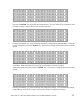
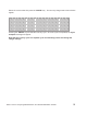
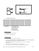
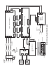
Battery Charger System Block Diagram