
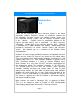
Specifications


XP250 INSTALLATION AND OPERATION MANUAL
Page 9
the charger and inverter are off.
Make DC input connections to the inverter as illustrated in
Appendix "B". Attach DC wires to the 2 pole female connector.
(Optional) Using 12-18 AWG wire, make Remote On/Off
connection from the rear panel terminal labeled "REMOTE" to one
pole of a small toggle switch. Then from the other pole of toggle
switch, make a connection to battery negative (-).
Make sure the toggle switch is off.
in order for the Remote On/Off switch to operate inverter,
On/Off switch on the front panel must be off.
If the appliance / load will be hard-wired to the inverter instead of
or in addition to the outlets provided on the front panel, see
Appendix "B".
.
.
.
.
.
2.
3.
4.
Note:
5.