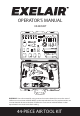
OPERATOR’S MANUAL EX4405KIT SPORTS NEEDLES PLUGS SAFETY NOZZLE TAPERED NOZZLE RUBBER NOZZLE GRINDING STONES WRENCHES TAPE SEAL OIL BOTTLE 50-PSI GAUGE 11 mm 9 mm COLLET 24 mm ADAPTOR 22 mm DUAL TIRE CHUCK EXTENSION BAR CHISELS 14 mm 17 mm IMPACT SOCKETS HAMMER IMPACT BLOW GUN DIE GRINDER RATCHET WARNING! Some dust created by using power tools contains chemicals known to the state of California to cause cancer and birth defects or other reproductive harm.
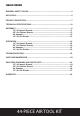
TABLE OF CONTENTS GENERAL SAFETY RULES.........................................................................................2 AIR SUPPLY..................................................................................................................5 PRODUCT DESCIPTION..............................................................................................7 TECHNICAL SPECIFICATIONS.................................................................................10 ASSEMBLY...........................
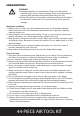
GENERAL SAFETY RULES WARNING! ● Improper operation or maintenance of this tool could result in personal injury and/or property damage. Read and understand all warnings and operation instructions before using this tool. ● When using this tool, these basic safety precautions should always be followed to reduce the risk of personal injury and/or property damage. Workplace conditons 1. Always work in a clean, dry, well-ventilated area free of combustible materials.
14. Never use the tool if it is defective, damaged, or operating abnormally. 15. Check for misalignment or binding of moving parts, breakage of parts and any other condition that affects the tool operation. If damaged, have the tool serviced before using. 16. Keep working parts of the tool away from hands and body. 17. Do not carry the tool by the air hose. 18. Do not apply excessive force of any kind to the tool. Let the tool perform the work at the rate as it was designed. 19.
4 Air ratchet wrench safety instructions 1. Always use the ratchet wrench in the manner and for the functions described in this manual. 2. Always ensure the wrench is not moving and disconnected from the air supply when changing sockets etc. Only use impact sockets. Do not use standard sockets. 3.
13. Always store this product in a dry and safe place out of reach of children or untrained operators. Air die grinder safety instructions 1. Always use the die grinder in the manner and for the functions described in this manual. 2. Always ensure the grinder is not moving and disconnected from the air supply when changing grinding stones etc. 3. Only use qualified grinding stones. Never use chipped or cracked grinding stones. 4.
9. Use proper hoses and fittings. We do not suggest connecting quick change couplings directly to the tool since they may cause failure due to tool vibration at operation. Instead, add a lead hose and connect coupling between air supply and hose whip. 10. Check hoses for wear before each use. Make certain that all connections are in security. 12 13 4 1 11 3 2 6 5 10 8 7 AIR SYSTEM LAYOUT: 1. Air Tool 2. Air Hose 3/8" (I.D.) 3. Oiler 4. Pressure Regulator 5. Filter 15 14 9 6. Shut Off Valve 7.
7 PRODUCT DESCRIPTION A B C D Y T S G PLUGS W U F SPORTS NEEDLES X V E SAFETY NOZZLE TAPERED NOZZLE RUBBER NOZZLE GRINDING STONES WRENCHES H TAPE SEAL OIL BOTTLE 50-PSI GAUGE 11 mm 9 mm COLLET 24 mm ADAPTOR 22 mm J CHISELS 14 mm 17 mm I DUAL TIRE CHUCK EXTENSION BAR IMPACT SOCKETS K R Q L HAMMER IMPACT P BLOW GUN DIE GRINDER O RATCHET M N PART A B C D E F G H I J K L M QUANTITY DESCRIPTION 1 Female Plug 1 Safety Nozzle 1 Tapered Nozzle 2 Sports needle 1 Rubber No
8 A1 F1 E1 D1 B1 C1 1/2" AIR IMPACT WRENCH A2 PART A1 B1 C1 D1 E1 F1 B2 QUANTITY DESCRIPTION 1 1/2" Air Impact Wrench 1 Forward/Reverse Rotation Control 1 Air Inlet 1 Trigger 1 Grease Cap 1 Anvil C2 D2 E2 F2 H2 3/8" AIR RATCHET WRENCH G2 PART A2 B2 C2 D2 E2 F2 G2 H2 DESCRIPTION F/R Knob Exhaust Deflector 3/8" Air Ratchet Wrench Steel Ball Air Inlet Air Regulator Trigger Anvil 44-PIECE AIR TOOL KIT QUANTITY 1 1 1 1 1 1 1 1
B3 9 C3 D3 A3 AIR HAMMER PART A3 B3 C3 D3 QUANTITY 1 1 1 1 DESCRIPTION Air Inlet Cylinder Air Hammer Trigger A4 B4 C4 D4 J4 I4 E4 H4 G4 1/4" AIR DIE GRINDER PART A4 B4 C4 D4 E4 F4 G4 H4 I4 J4 F4 DESCRIPTION Lever Trigger Exhaust Deflector Steel Ball Air Inlet Air Regulator 1/4" Air Die Grinder Collet Holder Collet Jacket Collet 44-PIECE AIR TOOL KIT QUANTITY 1 1 1 1 1 1 1 1 1 1
10 TECHNICAL SPECIFICATIONS 1/2" AIR IMPACT WRENCH COMPONENT Square drive Maximum no load speed Maximum torque Air inlet Air hose (inner diameter) Average air consumption Working pressure SPECIFICATIONS 1/2" 7,000rpm 500Ft-Lb (680Nm) 1/4" NPT 3/8" 6.5cfm 90psi (6.3bar) 3/8" AIR RATCHET WRENCH COMPONENT Square drive Maximum no load speed Maximum torque Air inlet Air hose (inner diameter) Average air consumption Working pressure SPECIFICATIONS 3/8" 160rpm 60Ft-Lb (85Nm) 1/4" NPT 3/8" 4cfm 90psi (6.
ASSEMBLY 1/2" AIR IMPACT WRENCH 11 1 1. Remove the air inlet protective cap from the air inlet (C1). (See Figure 1) C1 2. Mount a male plug by hand into the air inlet (C1). (See Figure 2) 2 NOTE: Use thread sealant tape on the male plug and tighten it with a wrench for airtight connection. Do not overtighten. 3. Place 2 - 3 drops of air tool oil into the male plug before each use.
4. Choose the correct impact socket (S) as needed and mount it onto the anvil (F1). (See Figure 4) WARNING! Only use impact sockets that have a RPM and Torque rating equal to or greater than the tool itself. 5. If necessary, use the 1/2" extension bar (V) and then mount impact socket onto the bar. (See Figure 5) 12 4 S F1 5 V S 6. Connect air supply hose to the male plug. (See Figure 6) 6 7. Set the working pressure at 90psi/6.3bar for best tool performance.
3/8" AIR RATCHET WRENCH 1. Remove the air inlet protective cap from the air inlet (E2). (See Figure 7) 13 7 E2 2. Mount the male plug by hand into the air inlet (E2). (See Figure 8) 8 NOTE: Use thread sealant tape on the male plug and tighten it with a wrench for airtight connection. Do not overtighten. 3. Place 2 - 3 drops of air tool oil into the male plug before each use.
4. Choose the correct impact socket (S) as needed and mount it onto the anvil (H2). (See Figure 10) WARNING! Only use impact sockets that have a RPM and Torque rating equal to or greater than the tool itself. 5. Connect air supply hose to the male plug. (See Figure 11) 14 10 S H2 11 6. Set the working pressure at 90psi/6.3bar for best tool performance. NOTE: Working pressure refers to the air line pressure set to tool when tool is under working conditions. AIR HAMMER 1.
2. Mount the male plug by hand into the air inlet (A3). (See Figure 13) 15 13 NOTE: Use thread sealant tape on the male plug and tighten it with a wrench for airtight connection. Do not overtighten. 3. Place 2 - 3 drops of air tool oil into the male plug before each use. (See Figure 14) 4. Insert a chisel (K) into the opening of cylinder (B3).
5. Screw the spring retainer (Q) onto the cylinder (B3) and firmly secure it. (See Figure 16) 16 16 B3 Q 6. Connect air supply hose to the male plug. (See Figure 17) 17 7. Set the working pressure at 90psi/6.3bar for best tool performance. NOTE: Working pressure refers to the air line pressure set to tool when tool is under working conditions. 1/4" AIR DIE GRINDER 1. Remove the air inlet protective cap from the air inlet (E4).
2. Mount a male plug by hand into the air inlet (E4). (See Figure 19) 17 19 NOTE: Use thread sealant tape on the male plug and tighten it with a wrench for airtight connection. Do not overtighten. 3. Place 2 - 3 drops of air tool oil into the male plug before each use. (See Figure 20) 4. Loosen the collet jacket (I4) counterclockwise by hand or with the large wrench while holding the small wrench on the flats of the collet holder (H4).
5. Insert a grinding stone (F/G) into the collet (J4). (See Figure 22) 22 NOTE: Two collets of different sizes (1/4", 1/8") are provided. Select whichever fits the shank of the stone you have chosen. 6. Tighten the collet jacket (I4) clockwise with large wrench while holding the small wrench on the flats of the collet holder (H4). Make sure that the grinding stone is installed securely and tightly.
OPERATION 1/2" AIR IMPACT WRENCH 1. How to install/tighten threaded fasteners. Push the Forward/Reverse rotation control (B1) forward and have the arrow on the Forward/ Reverse rotation control (B1) pointing at either of the three dots on the back housing as shown. Press the trigger (D1). The tool anvil (F1) runs clockwise. (See Figure 25) 2. How to remove/loosen threaded fasteners.
NOTE: This tool also features a grease cap (E) on the protector cover. Remove the screw in the grease cap (E1) with a hex key (not provided). Use a grease gun (not provided) and insert the gun nozzle into the grease cap (E1). Several drops of grease are recommended for lubricating the internal hammer assembly. This will help the hammer assembly to work in good condition and extend tool life. Lubricate the hammer assembly once every working day. (See Figure 28) 3/8" AIR RATCHET WRENCH 1.
NOTE: This tool features a power regulator valve. Rotate the air regulator (F2) until desired output is achieved. The settings 1, 2, 3, 4 are only for reference and do not denote a specific power output. “Setting 1” (one-line symbol) is the least amount of power while “Setting 4” (four-line symbol) is the most amount of power. Rotate the air regulator (F2) until the desired setting is lined up with the small steel ball (D2) on air inlet (E2).
1/4" AIR DIE GRINDER Push lever (A4) forward and press down on the trigger (B4) to start the tool (G4). (See Figure 34) 22 34 A4 B4 G4 NOTE: This tool features a power regulator valve. Rotate the air regulator (F4) until desired output is achieved. The settings 1, 2, 3, 4 are only for reference and do not denote a specific power output. “Setting 1” (one-line symbol) is the lowest speed while “Setting 4” (four-line symbol) is the highest speed.
TROUBLESHOOTING PROBLEM Tool runs slowly or will not operate POSSIBLE CAUSE 1. Grit or gum in tool. CORRECTIVE ACTION 1. Flush the tool with air-tool oil or gum solvent. 2. Lubricate the tool. 2. No oil in tool. 3. a. Adjust the regulator on the tool to 3. Low air pressure. maximum setting. b. Adjust the compressor regulator to tool maximum of 90 PSI/6.3 BAR. 4. Tighten and seal hose fittings if leaks are 4. Air hose leaks. found. Use sealing tape. 5. a. Be sure the hose is the proper size. 5.
EXPLODED DIAGRAM AND PARTS LIST 1/2" AIR IMPACT WRENCH Part No. 1 2 3 4 5 6 7 8 9 10 11 12 13 14 15 16 17 18 19 20 21 22 23 24 25 26 Description Description Qty. Qty. Part No.
EXPLODED DIAGRAM AND PARTS LIST 3/8" AIR RATCHET WRENCH 36 25 34 35 37 40 6 38 39 5 28 30 41 43 1 31 42 32 19 33 29 20 21 3 22 45 44 46 25 4 23 26 47 49 24 2 18 48 50 51 53 54 55 13 27 56 52 Part No.
26 EXPLODED DIAGRAM AND PARTS LIST AIR HAMMER 1 6 5 4 2 3 12 7 11 10 8 9 23 13 14 22 15 16 24 18 17 19 20 21 Part No. 1 2 3 4 5 6 7 8 9 10 11 12 Description Qty. 1 Housing* 1 Valve seat - EX0445AH1-05 1 Valve - EX0445AH1-06 1 End cap - EX0445AH1-07 1 Piston* 1 Cylinder* 1 Spring retainer* 1 Trigger sleeve* 1 Spring* 1 O-ring* 1 Trigger* 1 Set pin* Part No.
EXPLODED DIAGRAM AND PARTS LIST 27 1/4" AIR DIE GRINDER 38 37 36 35 34 3 4 5 2 26 28 33 32 31 30 6 17 26 18 29 27 25 39 40 24 23 21 20 22 14 13 7 8 Qty. 1 1 1 1 1 1 1 1 1 1 1 1 1 1 1 1 2 1 1 1 15 16 9 11 12 Description Housing* Trigger* Lever block* Spring* Bolt* Trigger pin* O-ring - EX1425DG1-08 O-ring - EX1425DG1-09 Valve stem* Spring* O-ring* Screw nut* Soft grip* Plastic cover* O-ring* Muffler* O-ring* Air regulator* O-ring* Air inlet* 19 1 10 Part No.
28 MILTON INDUSTRIES AIR TOOL WARRANTY POLICY 3 YEAR LIMITED WARRANTY Please visit www.miltonindustries.com to register this product for the 3-Year limited warranty offered by Milton. To make any warranty claims or to learn more about the 3 year warranty please visit www.miltonindustries.com For questions about our warranty on this product, contact us at: MILTON INDUSTRIES, INC. 4500 W. CORTLAND STREET, CHICAGO, IL 60639 Phone: 855-G04-MILT (855-464-6458) www.exel-air.