
User's Guide

User Guide
- 26 –
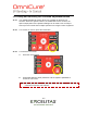
13 Interfacing with the S2000 PRO/ELITE
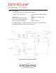
13.1 Connection Options
13.1.1 The S2000 PRO/ELITE is designed to be fully automated both quickly and
easily via PLC control or computer control using the RS-232 port. All of the
advanced features ensuring process control and curing repeatability can be
accessed through built in standard optically isolated I/O signals. Add info
13.1.2 Additionally, a stereo phono connector is available for a simple RS-232
radiometer connection on the front panel.
13.1.3 The PLC I/O’s, foot pedal and RS-232 port are optically isolated from the
control S2000 PRO/ELITE control electronics. This has been done in order to
maximize the S2000 PRO/ELITE’s immunity to noise and minimize its noise
output. Even the analog inputs and outputs (intensity monitor output and
intensity control input) are optically isolated from the control circuitry.
13.2 Input/ Output Signals and Descriptions
13.2.1 Output Signals
an output signal is said to be active when the output is ON
a signal is said to be ON when the transistor side of it’s respective optocoupler is
conducting current
the description of current conduction is dependant upon its’ end configuration,
selectable by the user
an output can be configured as active high in which case the transistor is
sourcing current, or active low in which case the transistor is sinking current
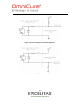
The "digital" outputs have the following characteristics:
>polarized type, output device: optocoupler, NPN transmitter
>logic Level: uncommitted emitter and collector can be
used as active high or active low
>maximum voltage withstand: 30VDC capability (Vce):
>maximum carry current: 8 mA
Note: Refer to the following page for examples of output signal circuit
configurations.
Note: a signal is said to be active when the transistor side output of the
optocoupler is on/conducting and inactive when the transistor side of
the optocoupler is off.