
Specifications
50
L510010-04
ENGINE MAINTENANCE - 11
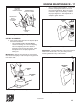
6. After the engine has been properly aligned,
secure the engine mounts.
7. Connect the propeller shaft coupling to the
transmission coupling. Tighten the coupling
attaching bolts and nuts to the correct
specifi cations.
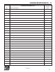
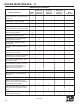
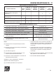
FASTENER TORQUE SPECIFICATIONS
Location Lb-Ft (N
.
m)
Engine Mount to Stringer Securely
Propeller 50 (68)
Trunnion Bolts 45 (61)
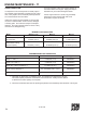
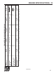
Figure 11-33 Angular Alignment
STRAIGHT
EDGE
TRANSMISSION
OUTPUT FLANGE
.003 INCH
(0.07 mm)
FEELER GAUGE
PROPELLER
SHAFT
COUPLING
FLANGE
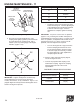
5. Check for any angular misalignment. Hold
coupling faces tightly together by hand and check
for a gap between the coupling faces, with a
0.003 in. (0.07 mm) feeler gauge, at 90-degree
intervals. (Figure 11-34).
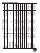
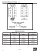
Figure 11-34 Angular Alignment Check
A
A
B
B
RC
RC
LC
LC
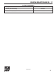
IMPORTANT: Angular misalignment conditions may
require adjustment of one front mount, both front
mounts, the trunnions, or any combination. Figure 11-34
(Angular Alignment Check) and the following table are to
assist in the alignment process.
Angular Misalignment Front Mount Adjusted
A Both
B Trunnion
LC R
RC L
• To adjust a corner of the engine up or down,
loosen the locking nut. Turn the adjusting nut
or the adjusting bolt in the direction required
to raise or lower the engine. After the
adjustment is complete, tighten the locking
nut.
IMPORTANT: If a “pinch” occurs in the “A” quadrant
(Figure 11-34), correcting the condition will require an
equal adjustment on the front mounts. If a “pinch” occurs
in the “C” quadrant, an adjustment will be made on the
opposing front mount. If a “pinch” occurs in the “B”
quadrant, a trunnion adjustment is required.
• To move the engine left or right, loosen the
trunnion clamping bolt and the nut on all
four mounting brackets. Move the engine
to the left or right, as necessary, to obtain
the proper alignment. After adjustment is
complete, tighten all bolts.