
Specifications

49
L510010-04
ENGINE MAINTENANCE - 11
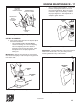
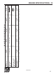
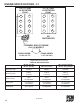
Figure 11-29 Angular Alignment
STRAIGHT
EDGE
TRANSMISSION
OUTPUT FLANGE
.003 INCH
(0.07 mm)
FEELER GAUGE
PROPELLER
SHAFT
COUPLING
FLANGE
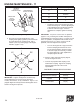
OFFSET ALIGNMENT:
4. If the coupler center lines are not aligned, adjust
the mounts as follows:
• UP or DOWN OFFSET ADJUSTMENT:
Loosen the locking nut. Turn the adjusting
nut or the adjusting bolt in the direction
required to raise or lower the engine. After
the adjustment is complete, tighten the
locking nut.
IMPORTANT: Both the front mounts (or rear mounts)
must be turned equally in order to keep the engine level
from side to side.
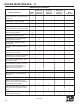
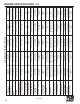
Figure 11-32 Engine Extension
TRUNNION
BOLT
1.0
(2
5
IMPORTANT: The large diameter of the mount trunnion
MUST NOT extend over 1.0 in. (25.4 mm) from the
mounting brackets on any of the mounts.
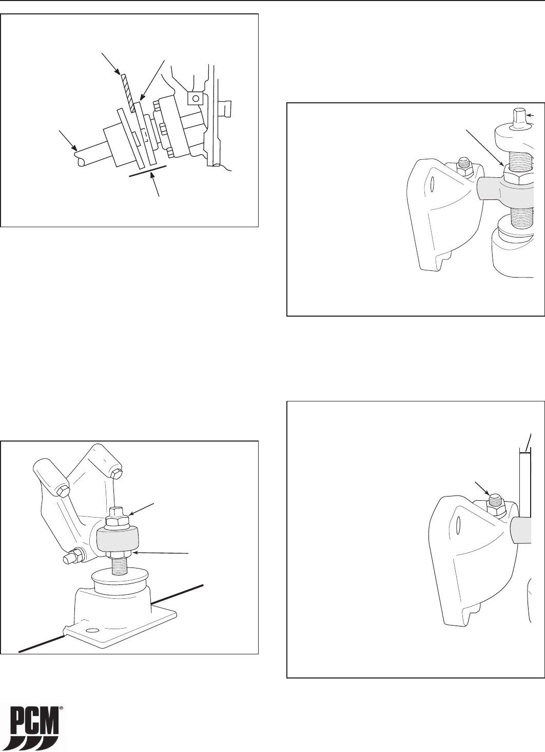
Figure 11-31 Mount Adjustment
LOCKING
NUT
• LEFT or RIGHT ADJUSTMENT: Loosen the
trunnion clamping bolt and the nut on all
four mounting brackets. Move the engine
to the left or right, as necessary, to obtain
the proper alignment. After adjustment is
complete, tighten all bolts.
Figure 11-30 Mount Adjustment
LOCKING
NUT
ADJUSTING
NUT