
User's Manual
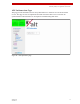


Table Of Contents
- ExtendAir® (TDD) Series Digital Microwave Radios Installation and Management Guide
- Legal Notice
- Open-Source License Information
- Table of Contents
- Notes for Customers of the Cisco Configuration ExtendAir r5005
- About this Document
- Introduction
- Pre-installation Tasks
- Link Engineering and Site Planning
- Familiarization with the ExtendAir (TDD) Series Radios
- Initial Configuration and Back-to-Back Bench Test
- Time Division Duplex (TDD) Factors
- Link Orientation and Synchronization
- Radio Synchronization
- Offset Timing
- Virtual Local Area Network (VLAN)
- Simple Network Management Protocol (SNMP)
- System Installation and Initiation Process
- Installation
- Configuration and Management
- Telnet into the Command Line Interface (CLI)
- Telnet
- Exalt Graphical User Interface (GUI)
- Quick Start
- Navigating the GUI
- Radio Information Page
- Administration Settings Page
- NTP and Time Zones Configurations Page
- Simple Network Management Protocol (SNMP) Configuration
- File Management Pages
- File Transfer Page
- File Activation Page
- System Configuration Page
- Ethernet Interface Configuration Page
- T1/E1 Configuration Pages
- VLAN Configuration Page
- Ethernet Rate Limiting
- QoS Configuration Page
- Automatic Channel Selection (ACS) Page
- Syslog Configuration Page
- GPS Information Page
- Alarms Page
- Performance Page
- Event Log Page
- User Throughput Page
- Diagnostic Charts Page
- Spectrum Analyzer Page
- Ethernet Utilization Page
- Reboot Page
- Manual Page
- Specifications
- Interface Connections
- Antennas
- Troubleshooting
- Back-to-back Bench Testing
- General Compliance and Safety
- Dynamic Frequency Selection
- Safety Notices
- Regulatory Notices
- Regulatory Compliance
- Regulatory Domain Keys
- EIRP Limits for the United States and Canada
- EIRP Limits for Australia
- EIRP Limits for the European Union and ITU Countries
- Declaration of Conformity to the R&TTE Directive 1999/5/EC
- Exalt Limited Hardware Warranty Software License and RMA Procedures Agreement
- Copyright Notices
- Index

Exalt Installation and Management Guide
ExtendAir (TDD) Series Digital Microwave Radios
72 203591-010
2012-09-04
Alarms Page
This page provides an easy-to-read summary of the alarm status of both local and remote radios. The
colors on this page reflect the color of the alarms displayed on the radio front panel. However,
additional detail displays on this page to aid in quick assessment of issues and status.
Figure 45 Alarms page
Table 6 lists alarm status conditions that appear on this page.
Table 6 Alarm status indicators
Label Status
Link Indicates RF link status:
• Green Solid = Error-free connection (BER<10e-6)
• Yellow Solid = Errored connection (10e-3>BER >10e-6)
• Red Solid = No link (BER>10e-3)
DFS (enabled models only) Indicates the status of the Dynamic Frequency Selection (DFS).
• Green = No DFS activity, normal transmission
• Red = Either CAC or NOP is in progress.
Collocation Indicates the enabled/disabled status with Internal or GPS sync and current alarm status.
• Green Solid = Sync enabled and sync input present
• Yellow Solid = Sync enabled and missing proper sync input in flywheel operation period
• Red Solid = Sync enabled and missing proper sync input signal and flywheel period
expired