
User's Manual

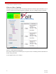


Table Of Contents
- ExtendAir® (TDD) Series Digital Microwave Radios Installation and Management Guide
- Legal Notice
- Open-Source License Information
- Table of Contents
- Notes for Customers of the Cisco Configuration ExtendAir r5005
- About this Document
- Introduction
- Pre-installation Tasks
- Link Engineering and Site Planning
- Familiarization with the ExtendAir (TDD) Series Radios
- Initial Configuration and Back-to-Back Bench Test
- Time Division Duplex (TDD) Factors
- Link Orientation and Synchronization
- Radio Synchronization
- Offset Timing
- Virtual Local Area Network (VLAN)
- Simple Network Management Protocol (SNMP)
- System Installation and Initiation Process
- Installation
- Configuration and Management
- Telnet into the Command Line Interface (CLI)
- Telnet
- Exalt Graphical User Interface (GUI)
- Quick Start
- Navigating the GUI
- Radio Information Page
- Administration Settings Page
- NTP and Time Zones Configurations Page
- Simple Network Management Protocol (SNMP) Configuration
- File Management Pages
- File Transfer Page
- File Activation Page
- System Configuration Page
- Ethernet Interface Configuration Page
- T1/E1 Configuration Pages
- VLAN Configuration Page
- Ethernet Rate Limiting
- QoS Configuration Page
- Automatic Channel Selection (ACS) Page
- Syslog Configuration Page
- GPS Information Page
- Alarms Page
- Performance Page
- Event Log Page
- User Throughput Page
- Diagnostic Charts Page
- Spectrum Analyzer Page
- Ethernet Utilization Page
- Reboot Page
- Manual Page
- Specifications
- Interface Connections
- Antennas
- Troubleshooting
- Back-to-back Bench Testing
- General Compliance and Safety
- Dynamic Frequency Selection
- Safety Notices
- Regulatory Notices
- Regulatory Compliance
- Regulatory Domain Keys
- EIRP Limits for the United States and Canada
- EIRP Limits for Australia
- EIRP Limits for the European Union and ITU Countries
- Declaration of Conformity to the R&TTE Directive 1999/5/EC
- Exalt Limited Hardware Warranty Software License and RMA Procedures Agreement
- Copyright Notices
- Index

Exalt Installation and Management Guide
ExtendAir (TDD) Series Digital Microwave Radios
203591-010 69
2012-09-04
The status fields have the following color indicators:
• Red/Inactive: The channel is configured, but is not currently in use by the system. The radio is not
currently tuned to this channel.
• Yellow/Active without Link: The channel is configured and the radio is tuned to that channel, but
has not established a link with the other end.
• Green/Active with Link: The channel is configured, and the radio is tuned to that channel and has
established a link with the other end.
• Black/Temporarily inactive: DFS is enabled and the system detected a qualified DFS radar in this
channel, the channel is disabled for 30 minutes.
The system selects alternate channels sequentially. If the radio is operating on Channel #1, it selects
Channel #2 first, then Channel #3, and so on, until a link is re-established with the far-end. If the radio
is operating a channel other than Channel #1 and the Treat first entry as preferred option is selected,
the search always starts with Channel #1. Otherwise the search is sequential starting from the channel
of the operating frequency.
Radio A wait times are approximately 35 seconds per channel switch. Radio B channel switch wait
times are approximately 7 seconds. Radio B is listening for Radio A on each frequency, and may cycle
through the channel list multiple times before Radio A is detected and the link re-established. Wait
times are affected by this, and can be as long as 3 minutes, assuming that a link can be established on
at least one frequency on the enabled list. Adjusting BER thresholds to a higher BER value such as
10(-3) can improve wait times.
The BER threshold and time above BER threshold options trigger channel switching when ACS is
enabled. Available BER threshold options are from 10(–3) to 10(–7). The time above BER options are
in increments from 1 to 200 seconds. The defaults are 10(–5) and 10 seconds, respectively. Adjusting
BER thresholds to a higher BER level and/or increasing the timer length for BER, reduces ACS
activity.
All ACS events are captured in the event log and can be accessed in real time for troubleshooting.
Corresponding status alarms are also captured in the event log and display on the Alarms Page
.
• ACS must be enabled on the System Configuration Page on both radios or the link may
be permanently lost.
• To avoid link loss, include a setting for the current frequency before enabling ACS.
When Dynamic Frequency Selection (DFS) is enabled due to regulations, expect an
additional one minute wait time per channel switch. For some regulatory domains, the wait
time is increased to 6 minutes per channel switch for certain frequencies.