
User's Manual
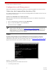


Table Of Contents
- ExtendAir® (TDD) Series Digital Microwave Radios Installation and Management Guide
- Legal Notice
- Open-Source License Information
- Table of Contents
- Notes for Customers of the Cisco Configuration ExtendAir r5005
- About this Document
- Introduction
- Pre-installation Tasks
- Link Engineering and Site Planning
- Familiarization with the ExtendAir (TDD) Series Radios
- Initial Configuration and Back-to-Back Bench Test
- Time Division Duplex (TDD) Factors
- Link Orientation and Synchronization
- Radio Synchronization
- Offset Timing
- Virtual Local Area Network (VLAN)
- Simple Network Management Protocol (SNMP)
- System Installation and Initiation Process
- Installation
- Configuration and Management
- Telnet into the Command Line Interface (CLI)
- Telnet
- Exalt Graphical User Interface (GUI)
- Quick Start
- Navigating the GUI
- Radio Information Page
- Administration Settings Page
- NTP and Time Zones Configurations Page
- Simple Network Management Protocol (SNMP) Configuration
- File Management Pages
- File Transfer Page
- File Activation Page
- System Configuration Page
- Ethernet Interface Configuration Page
- T1/E1 Configuration Pages
- VLAN Configuration Page
- Ethernet Rate Limiting
- QoS Configuration Page
- Automatic Channel Selection (ACS) Page
- Syslog Configuration Page
- GPS Information Page
- Alarms Page
- Performance Page
- Event Log Page
- User Throughput Page
- Diagnostic Charts Page
- Spectrum Analyzer Page
- Ethernet Utilization Page
- Reboot Page
- Manual Page
- Specifications
- Interface Connections
- Antennas
- Troubleshooting
- Back-to-back Bench Testing
- General Compliance and Safety
- Dynamic Frequency Selection
- Safety Notices
- Regulatory Notices
- Regulatory Compliance
- Regulatory Domain Keys
- EIRP Limits for the United States and Canada
- EIRP Limits for Australia
- EIRP Limits for the European Union and ITU Countries
- Declaration of Conformity to the R&TTE Directive 1999/5/EC
- Exalt Limited Hardware Warranty Software License and RMA Procedures Agreement
- Copyright Notices
- Index

Exalt Installation and Management Guide
ExtendAir (TDD) Series Digital Microwave Radios
203591-010 31
2012-09-04
the antennas before the radio equipment is delivered. However, many installers successfully use the
radios as the means for antenna alignment.
The following are the primary facilities when using the radio to align the antenna:
• RSL voltage connection using a volt meter (recommended)
Insert the included adapter into the GPS connector on the radio housing and the opposite end
connected to a volt meter.
The RSL test point DC voltage is inversely proportional and numerically calibrated to the received
signal level. The voltage rises as the antennas are less in alignment, and falls as antennas are more
in alignment. The voltage measurement corresponds to the received signal level in measurements
of dBm (a negative number for RSL measurements). For example, an RSL of -60dBm yields an
RSL voltage measurement of 0.60VDC; an RSL of –45dBm measures 0.45VDC.
• Audio alignment buzzer
Enable the audio alignment buzzer through the Exalt GUI. When enabled, the radio enclosure
emits a sound. The pitch rises when higher (better) levels of RSL are achieved. Align the antennas
until the highest pitch is accomplished. The tone is continuous when the two ends of the radio
system are in communication. Otherwise, the buzzer beeps.
• Exalt GUI RSL reading indicates the current RSL in dBm.
Note: There is a slight delay in RSL readings in the GUI as the RSL levels change. In this
case, fine alignment can be done in small adjustments allowing a small gap of time so that the
impact of the adjustment on the GUI display catches up to real time.
Note: Only use the browser-based GUI for antenna alignment if there are no other means
available. If this method is required, refer to Exalt Graphical User Interface (GUI)
. The RSL
reading can be read on a PC or any handheld computing device that supports an HTML
browser and Ethernet connectivity.