
User Manual


Table Of Contents
- ExtendAir® (TDD) Series Digital Microwave Radios Installation and Management Guide
- Legal Notice
- Open-Source License Information
- Table of Contents
- Notes for Customers of the Cisco Configuration ExtendAir r5005
- About this Document
- Introduction
- Pre-installation Tasks
- Link Engineering and Site Planning
- Familiarization with the ExtendAir (TDD) Series Radios
- Initial Configuration and Back-to-Back Bench Test
- Time Division Duplex (TDD) Factors
- Link Orientation and Synchronization
- Radio Synchronization
- Offset Timing
- Virtual Local Area Network (VLAN)
- Simple Network Management Protocol (SNMP)
- System Installation and Initiation Process
- Installation
- Configuration and Management
- Telnet into the Command Line Interface (CLI)
- Telnet
- Exalt Graphical User Interface (GUI)
- Quick Start
- Navigating the GUI
- Radio Information Page
- Administration Settings Page
- NTP and Time Zones Configurations Page
- Simple Network Management Protocol (SNMP) Configuration
- File Management Pages
- File Transfer Page
- File Activation Page
- System Configuration Page
- Ethernet Interface Configuration Page
- T1/E1 Configuration Pages
- VLAN Configuration Page
- Ethernet Rate Limiting
- QoS Configuration Page
- Automatic Channel Selection (ACS) Page
- Syslog Configuration Page
- GPS Information Page
- Alarms Page
- Performance Page
- Event Log Page
- User Throughput Page
- Diagnostic Charts Page
- Spectrum Analyzer Page
- Ethernet Utilization Page
- Reboot Page
- Manual Page
- Specifications
- Interface Connections
- Antennas
- Troubleshooting
- Back-to-back Bench Testing
- General Compliance and Safety
- Dynamic Frequency Selection
- Safety Notices
- Regulatory Notices
- Regulatory Compliance
- EIRP Limits for the United States and Canada
- EIRP Limits for Australia
- EIRP Limits for the European Union and ITU Countries
- Declaration of Conformity to the R&TTE Directive 1999/5/EC
- Exalt Limited Hardware Warranty Software License and RMA Procedures Agreement
- Copyright Notices
- Index
Exalt Installation and Management Guide
ExtendAir (TDD) Series Digital Microwave Radios
74 203591-011
2013-02-22
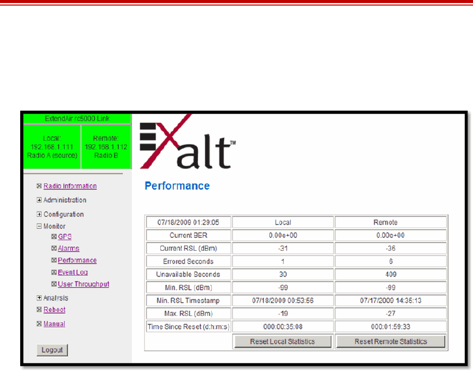
Performance Page
This page provides statistical information about the performance of the system in relation to the
integrity of the user data and the RF link.
Figure 46 Performance page
• The Current BER field indicates the current bit error rate of the link. If the link is operating
perfectly, this should indicate zero. Generally, the link should remain at a BER less than 1x10
-6
(1
bit out of every million bits errored). This is the threshold performance specification and the
standard to which the link was engineered. However, radio links can and are affected by weather,
interference, and other external sources and will occasionally have a higher error rate. A link
remains operational unless the BER exceeds 1x10
-3
(1 bit out of every hundred bits errored).
Consult the link design engineer for an understanding of the predicted error rate of the radio link as
it has been designed.
Many applications are unaffected by bit errors, but TDM circuits (for example, T1 or E1) are more
sensitive. Also, if the link operator is providing a service guarantee, this value may need to be
monitored or examined in cases of service issues. The behavior of BER in relation to other alarms
or measurements and external events can be very helpful in troubleshooting activities.
• Current RSL is the measurement of the received signal level at the radio antenna port. This is the
measured level of the RF signal coming from the opposite end of the radio link. The link was
engineered to a specific RSL by the link design engineer, and this RSL should be obtained during
installation and remain relatively stable during the operation of the link. RSL can and will vary as
a result of weather changes and other external sources, such as path obstructions. Once again, this
variation was part of the original design to achieve a certain level of performance over time. Bit
errors occur when the RSL falls to a level within roughly 3dB of the threshold specification. When
the RSL falls below the threshold specification, the link disconnects and will not reconnect until
the RSL is above the threshold specification. The behavior of RSL in relation to other alarms or
measurements and external events can be very helpful in troubleshooting activities.