
User Manual


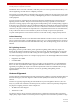
Table Of Contents
- ExtendAir® (TDD) Series Digital Microwave Radios Installation and Management Guide
- Legal Notice
- Open-Source License Information
- Table of Contents
- Notes for Customers of the Cisco Configuration ExtendAir r5005
- About this Document
- Introduction
- Pre-installation Tasks
- Link Engineering and Site Planning
- Familiarization with the ExtendAir (TDD) Series Radios
- Initial Configuration and Back-to-Back Bench Test
- Time Division Duplex (TDD) Factors
- Link Orientation and Synchronization
- Radio Synchronization
- Offset Timing
- Virtual Local Area Network (VLAN)
- Simple Network Management Protocol (SNMP)
- System Installation and Initiation Process
- Installation
- Configuration and Management
- Telnet into the Command Line Interface (CLI)
- Telnet
- Exalt Graphical User Interface (GUI)
- Quick Start
- Navigating the GUI
- Radio Information Page
- Administration Settings Page
- NTP and Time Zones Configurations Page
- Simple Network Management Protocol (SNMP) Configuration
- File Management Pages
- File Transfer Page
- File Activation Page
- System Configuration Page
- Ethernet Interface Configuration Page
- T1/E1 Configuration Pages
- VLAN Configuration Page
- Ethernet Rate Limiting
- QoS Configuration Page
- Automatic Channel Selection (ACS) Page
- Syslog Configuration Page
- GPS Information Page
- Alarms Page
- Performance Page
- Event Log Page
- User Throughput Page
- Diagnostic Charts Page
- Spectrum Analyzer Page
- Ethernet Utilization Page
- Reboot Page
- Manual Page
- Specifications
- Interface Connections
- Antennas
- Troubleshooting
- Back-to-back Bench Testing
- General Compliance and Safety
- Dynamic Frequency Selection
- Safety Notices
- Regulatory Notices
- Regulatory Compliance
- EIRP Limits for the United States and Canada
- EIRP Limits for Australia
- EIRP Limits for the European Union and ITU Countries
- Declaration of Conformity to the R&TTE Directive 1999/5/EC
- Exalt Limited Hardware Warranty Software License and RMA Procedures Agreement
- Copyright Notices
- Index
Exalt Installation and Management Guide
ExtendAir (TDD) Series Digital Microwave Radios
203591-011 29
2013-02-22
It is critical that the transmission line and antenna be capable of supporting the same type of connector,
or easily adapted. It can be important to minimize the number of connectors and adapters, and it is
ideal that they match directly without adaptation. In most cases, transmission line allows for N-type
male connectors and antennas have N-type female connectors.
If possible, connect the primary transmission line directly to the antenna. It is desired to have the
fewest possible pieces of transmission line in the system, to minimize losses and points of failure from
connectors. The antenna can typically accommodate a direct connection if planned in advance. Use a
90º adapter for the connection to the antenna, if necessary, but confirm that all connectors and
transmission lines are properly specified for the operating frequency with minimum loss, proper
impedance (50 Ohm) and proper VSWR characteristics.
Transmission line connector termination is a critical element of the installation. Many ‘factory built’
RF transmission lines do not provide the proper characteristics for proper transmission, despite their
published specifications, often due to the fully or semi-automated process of factory termination,
which may not have considered the frequency of your system. When buying pre-terminated
transmission line, it is strongly advised to obtain the documentation of test measurements on the
connected transmission line showing that the loss characteristics and VSWR are within the specified
limits specifically at your operating frequency. In addition to factory-built transmission line, self-
terminated transmission line can suffer the same issues.
The manufacturers of transmission line typically offer instruction and certification for transmission
line termination, and may also provide videos illustrating the process. There is no amount of extra care,
education, precision, and effort that can be overstated for this process.
There is often a need for a small excess of transmission line near the antenna to accommodate both the
need for extra slack as the antenna is loosened and moved for the alignment process, and to
accommodate a drip loop for the transmission line and the initial transmission line securing hardware
and grounding near the antenna. In addition, the transmission line is typically very stiff, and can
provide undue pulling force on the antenna or radio connector. Take care to align the cable with the
connector so that it does not provide any torque or strain on the connector.
Consult your transmission line manufacturer for the proper transportation, hoisting, securing, and
grounding process. Always be very mindful of the entire length of transmission line to ensure that the
transmission line is never twisted, kinked, or over-bent beyond the specified bend radius. Once a
Table 4 Recommended transmission line
Manufacturer Type Description Loss at 4.9GHz Loss at 5.3GHz Loss at 5.8GHz
Andrew LDF4-50 1/2-inch solid shield 5.6dB/100' 5.7dB/100' 6.0dB/100'
Andrew LDF4.5-50 5/8-inch solid shield N/A 4.4dB/100' 4.7dB/100'
Times LMR-600 1/2-inch braided shield 6.8dB/100' 6.9dB/100' 7.3dB/100'
Times LMR-900 5/8-inch braided shield N/A 4.6dB/100' 4.9dB/100'
RFS LCF12-50J 1/2-inch solid shield 5.5dB/100' 5.6dB/100' 5.9dB/100'
RFS LCF12-58J 5/8-inch solid shield N/A 4.5dB/100' 4.8dB/100'
Caution: Always follow the manufacturer’s termination process EXACTLY, and only use the
manufacturer’s authorized tools and connectors for a given transmission line type.