
User Manual


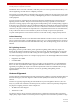
Table Of Contents
- ExtendAir® (TDD) Series Digital Microwave Radios Installation and Management Guide
- Legal Notice
- Open-Source License Information
- Table of Contents
- Notes for Customers of the Cisco Configuration ExtendAir r5005
- About this Document
- Introduction
- Pre-installation Tasks
- Link Engineering and Site Planning
- Familiarization with the ExtendAir (TDD) Series Radios
- Initial Configuration and Back-to-Back Bench Test
- Time Division Duplex (TDD) Factors
- Link Orientation and Synchronization
- Radio Synchronization
- Offset Timing
- Virtual Local Area Network (VLAN)
- Simple Network Management Protocol (SNMP)
- System Installation and Initiation Process
- Installation
- Configuration and Management
- Telnet into the Command Line Interface (CLI)
- Telnet
- Exalt Graphical User Interface (GUI)
- Quick Start
- Navigating the GUI
- Radio Information Page
- Administration Settings Page
- NTP and Time Zones Configurations Page
- Simple Network Management Protocol (SNMP) Configuration
- File Management Pages
- File Transfer Page
- File Activation Page
- System Configuration Page
- Ethernet Interface Configuration Page
- T1/E1 Configuration Pages
- VLAN Configuration Page
- Ethernet Rate Limiting
- QoS Configuration Page
- Automatic Channel Selection (ACS) Page
- Syslog Configuration Page
- GPS Information Page
- Alarms Page
- Performance Page
- Event Log Page
- User Throughput Page
- Diagnostic Charts Page
- Spectrum Analyzer Page
- Ethernet Utilization Page
- Reboot Page
- Manual Page
- Specifications
- Interface Connections
- Antennas
- Troubleshooting
- Back-to-back Bench Testing
- General Compliance and Safety
- Dynamic Frequency Selection
- Safety Notices
- Regulatory Notices
- Regulatory Compliance
- EIRP Limits for the United States and Canada
- EIRP Limits for Australia
- EIRP Limits for the European Union and ITU Countries
- Declaration of Conformity to the R&TTE Directive 1999/5/EC
- Exalt Limited Hardware Warranty Software License and RMA Procedures Agreement
- Copyright Notices
- Index
Exalt Installation and Management Guide
ExtendAir (TDD) Series Digital Microwave Radios
22 203591-011
2013-02-22
Radio Ports and Indicators
This section provides a brief overview of the connectors, controls, and indicators on the device. Details
about each item are in other sections of this document. Figure 11 shows the connectors on the
ExtendAir (TDD) Series radios.
Figure 11 ExtendAir (TDD) Series connectors (model r5000)
Connector Overview
The primary user interfaces are shown in Figure 12. Table 2 provides details of the connectors.
Detailed pin structures for each connector are in Interface Connections
.
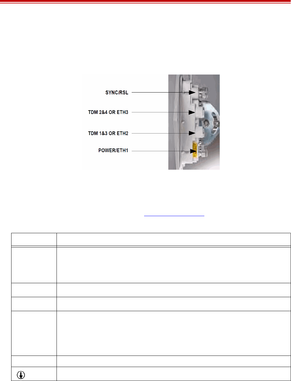
Table 2 Connectors
Connector Description
SYNC/RSL (1) Sync In for TDD Synchronization (from Exalt GPS or second radio or ExaltSync Collocation Kit).
(2) Sync Out for TDD Synchronization (to a second radio or through ExaltSync Collocation Kit to
multiple radios).
(3) Antenna alignment RSL voltage (during installation).
TDM 2&4 Ports for up to two user T1 or E1 circuits to traverse link, port numbers 2 and 4.
TDM 1&3 Ports for up to two user T1 or E1 circuits to traverse link, port numbers 1 and 3.
Power/ETH1 Connected cables traverse to the power injector (Data+Power side), and provide the following
functions:
• Primary ports for user Ethernet data (10BaseT or 100BaseT) to traverse link
• DC power from power injector
ETH2 and ETH3 Ports for additional Ethernet connections, management and/or traffic. (xx05 models only).
(Ground) Threaded (M5) receptacle.