
User Manual


Table Of Contents
- ExtendAir® (TDD) Series Digital Microwave Radios Installation and Management Guide
- Legal Notice
- Open-Source License Information
- Table of Contents
- Notes for Customers of the Cisco Configuration ExtendAir r5005
- About this Document
- Introduction
- Pre-installation Tasks
- Link Engineering and Site Planning
- Familiarization with the ExtendAir (TDD) Series Radios
- Initial Configuration and Back-to-Back Bench Test
- Time Division Duplex (TDD) Factors
- Link Orientation and Synchronization
- Radio Synchronization
- Offset Timing
- Virtual Local Area Network (VLAN)
- Simple Network Management Protocol (SNMP)
- System Installation and Initiation Process
- Installation
- Configuration and Management
- Telnet into the Command Line Interface (CLI)
- Telnet
- Exalt Graphical User Interface (GUI)
- Quick Start
- Navigating the GUI
- Radio Information Page
- Administration Settings Page
- NTP and Time Zones Configurations Page
- Simple Network Management Protocol (SNMP) Configuration
- File Management Pages
- File Transfer Page
- File Activation Page
- System Configuration Page
- Ethernet Interface Configuration Page
- T1/E1 Configuration Pages
- VLAN Configuration Page
- Ethernet Rate Limiting
- QoS Configuration Page
- Automatic Channel Selection (ACS) Page
- Syslog Configuration Page
- GPS Information Page
- Alarms Page
- Performance Page
- Event Log Page
- User Throughput Page
- Diagnostic Charts Page
- Spectrum Analyzer Page
- Ethernet Utilization Page
- Reboot Page
- Manual Page
- Specifications
- Interface Connections
- Antennas
- Troubleshooting
- Back-to-back Bench Testing
- General Compliance and Safety
- Dynamic Frequency Selection
- Safety Notices
- Regulatory Notices
- Regulatory Compliance
- EIRP Limits for the United States and Canada
- EIRP Limits for Australia
- EIRP Limits for the European Union and ITU Countries
- Declaration of Conformity to the R&TTE Directive 1999/5/EC
- Exalt Limited Hardware Warranty Software License and RMA Procedures Agreement
- Copyright Notices
- Index
Exalt Installation and Management Guide
ExtendAir (TDD) Series Digital Microwave Radios
203591-011 21
2013-02-22
Installation
This section presents all tasks required to install the Exalt Digital Microwave Radio.
Mechanical Configuration and Mounting
The ExtendAir (TDD) Series radios are environmentally sealed units intended for deployment
outdoors. The device must be deployed within an ambient temperature range as specified, and with
non-restrictive airflow around the chassis. The rc models can also be mounted in an enclosure or
indoors. The same airflow and temperature conditions apply. All integrated antenna models can be
mounted behind a window if window losses are considered in the link budget calculation.
Provide proper clearance for all cables and connectors attached to the device.
Note that for the rc models, the RF cable connector may require significant clearance for the bend
radius of the coaxial cable assembly. All RF connectors, cables, and adapters must be rated for
operation within the radio’s frequency range. RF connector losses must be accounted for within the
link engineering design and output power settings.
Mounting the System
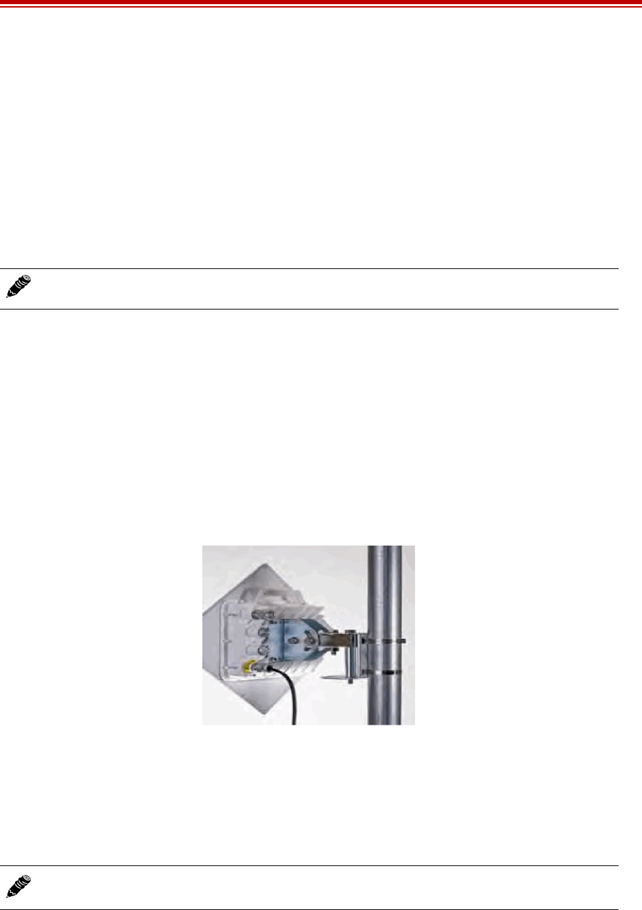
Use the mounting system supplied with each terminal for wall or pole mounting (Figure 10). The pole
mounting kit can accommodate a pole 2–5"/5–13cm in diameter. Install the mounting system first, and
then affix the radio to the mount. The radio can also be affixed to the mount, and the entire assembly
(including radio) mounted.
Figure 10 Pole-mount example (integrated antenna version)
For rc models, the mounting solution is a very simple single bracket, using the same pole-mounting
band clamps with the same specifications.
For the integrated antenna model, it is critical to mount the entire device at the predetermined location
for proper path clearance to the link end. Ensure that there is adequate space around the mounting
system and the radio to allow for antenna alignment for both azimuth and elevation adjustments.
Note: The power injector and power supply must be placed indoors or in an enclosure.
Note: Mount the rc models as close as possible to the antenna to minimize the length and
associated losses of RF cabling.