
User Manual


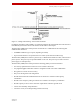


Table Of Contents
- ExtendAir® (TDD) Series Digital Microwave Radios Installation and Management Guide
- Legal Notice
- Open-Source License Information
- Table of Contents
- Notes for Customers of the Cisco Configuration ExtendAir r5005
- About this Document
- Introduction
- Pre-installation Tasks
- Link Engineering and Site Planning
- Familiarization with the ExtendAir (TDD) Series Radios
- Initial Configuration and Back-to-Back Bench Test
- Time Division Duplex (TDD) Factors
- Link Orientation and Synchronization
- Radio Synchronization
- Offset Timing
- Virtual Local Area Network (VLAN)
- Simple Network Management Protocol (SNMP)
- System Installation and Initiation Process
- Installation
- Configuration and Management
- Telnet into the Command Line Interface (CLI)
- Telnet
- Exalt Graphical User Interface (GUI)
- Quick Start
- Navigating the GUI
- Radio Information Page
- Administration Settings Page
- NTP and Time Zones Configurations Page
- Simple Network Management Protocol (SNMP) Configuration
- File Management Pages
- File Transfer Page
- File Activation Page
- System Configuration Page
- Ethernet Interface Configuration Page
- T1/E1 Configuration Pages
- VLAN Configuration Page
- Ethernet Rate Limiting
- QoS Configuration Page
- Automatic Channel Selection (ACS) Page
- Syslog Configuration Page
- GPS Information Page
- Alarms Page
- Performance Page
- Event Log Page
- User Throughput Page
- Diagnostic Charts Page
- Spectrum Analyzer Page
- Ethernet Utilization Page
- Reboot Page
- Manual Page
- Specifications
- Interface Connections
- Antennas
- Troubleshooting
- Back-to-back Bench Testing
- General Compliance and Safety
- Dynamic Frequency Selection
- Safety Notices
- Regulatory Notices
- Regulatory Compliance
- EIRP Limits for the United States and Canada
- EIRP Limits for Australia
- EIRP Limits for the European Union and ITU Countries
- Declaration of Conformity to the R&TTE Directive 1999/5/EC
- Exalt Limited Hardware Warranty Software License and RMA Procedures Agreement
- Copyright Notices
- Index

Exalt Installation and Management Guide
ExtendAir (TDD) Series Digital Microwave Radios
10 203591-011
2013-02-22
• The shorter the link distance, the lower the latency, the higher the throughput
• The longer the TDD frame size, the higher the throughput
• The higher the bandwidth, the higher the capacity
• The higher the mode, the higher the capacity
Link Orientation and Synchronization
Link orientation refers to the Radio A and Radio B placement in your network. Link synchronization
refers to using external or internal timing to coordinate multiple links.
For every link, one end of the radio link must be configured as Radio A, while the other end is
configured as Radio B. In single-link systems, it does not matter which end of the system is mounted at
which end of the link, and there is typically no requirement for any link synchronization.
Link orientation and synchronization are more important for networks with site(s) where there is more
than one link of the same type or for sites using the same type of radio that are very close to each
another at one or both ends.
Configure collocated radio terminals for the same link orientation. That is, configure all radios at the
same location as Radio A or Radio B.
It can be advantageous to utilize link synchronization for collocated links. The radios allow the use of
an optional GPS synchronization kit. This synchronization controls the transmitter and receiver frame
timing so that collocated radios are transmitting at the same time and receiving at the same time. This
can substantially reduce the opportunity for self-interference. Without synchronization, collocated
radios may be transmitting and receiving at the same time, incurring near-end interference.
When synchronization is required or desired, the following configurations are recommended:
• For a two-radio network without GPS, use Internal Sync and connect a single cable between the
SYNC/RSL ports on both radios (see RSL/Sync Connector
for wiring instructions).
• For a two-radio network using GPS sync, use two GPS kits or one GPS kit and the ExaltSync
Collocation kit.
Note: Disable all T1/E1 ports if there are no T1/E1 interfaces connected. This shifts all available
throughput to the Ethernet interface.
Note: If a selected combination of the Link Distance, Frame Size, Bandwidth, and Mode
parameters cannot support all the desired T1 or E1 ports, the ports that cannot be supported are
automatically disabled. Priority is placed on the T1/E1 port number. That is, the first port to be
disabled, if necessary, is the highest port number, such as Port 4. See T1/E1 Configuration Pages
for more information.
Note: It is not always necessary to synchronize collocated radios. If antennas are substantially
separated or blocked from one another and/or frequency separation tuning is used, the
opportunity for near-end interference can be eliminated.
Note: Refer to the ExaltSync Collocation Expansion Kit Quick Start Guide for instructions.