
User Manual
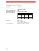


Table Of Contents
- ExtendAir® (TDD) Series Digital Microwave Radios Installation and Management Guide
- Legal Notice
- Open-Source License Information
- Table of Contents
- Notes for Customers of the Cisco Configuration ExtendAir r5005
- About this Document
- Introduction
- Pre-installation Tasks
- Link Engineering and Site Planning
- Familiarization with the ExtendAir (TDD) Series Radios
- Initial Configuration and Back-to-Back Bench Test
- Time Division Duplex (TDD) Factors
- Link Orientation and Synchronization
- Radio Synchronization
- Offset Timing
- Virtual Local Area Network (VLAN)
- Simple Network Management Protocol (SNMP)
- System Installation and Initiation Process
- Installation
- Configuration and Management
- Telnet into the Command Line Interface (CLI)
- Telnet
- Exalt Graphical User Interface (GUI)
- Quick Start
- Navigating the GUI
- Radio Information Page
- Administration Settings Page
- NTP and Time Zones Configurations Page
- Simple Network Management Protocol (SNMP) Configuration
- File Management Pages
- File Transfer Page
- File Activation Page
- System Configuration Page
- Ethernet Interface Configuration Page
- T1/E1 Configuration Pages
- VLAN Configuration Page
- Ethernet Rate Limiting
- QoS Configuration Page
- Automatic Channel Selection (ACS) Page
- Syslog Configuration Page
- GPS Information Page
- Alarms Page
- Performance Page
- Event Log Page
- User Throughput Page
- Diagnostic Charts Page
- Spectrum Analyzer Page
- Ethernet Utilization Page
- Reboot Page
- Manual Page
- Specifications
- Interface Connections
- Antennas
- Troubleshooting
- Back-to-back Bench Testing
- General Compliance and Safety
- Dynamic Frequency Selection
- Safety Notices
- Regulatory Notices
- Regulatory Compliance
- EIRP Limits for the United States and Canada
- EIRP Limits for Australia
- EIRP Limits for the European Union and ITU Countries
- Declaration of Conformity to the R&TTE Directive 1999/5/EC
- Exalt Limited Hardware Warranty Software License and RMA Procedures Agreement
- Copyright Notices
- Index
Exalt Installation and Management Guide
ExtendAir (TDD) Series Digital Microwave Radios
96 203591-011
2013-02-22
Figure 57 RSL & Sync In/Sync Out connector
Two Radio Internal Sync Out/In
If using the Internal Sync Out/In function between two radios only, connect Pin 8 from the Sync Out
radio to Pin 6 of the Sync In radio and use a straight connection for Pin 2. Connect no other pins. To
ease the need to keep track of which end of the cable is for In and Out, consider cross-connecting Pins
6 and 8, with a straight connection for Pin 2. Connect no other pins.
Sync Distribution Accessory
If using a sync distribution accessory (sold separately), connect CAT5e cabling straight from the radio
Sync connector(s) to the accessory.
Power/Ethernet Connector
This connector is the primary connector on the radio, and must be connected to provide power to the
radio, and primary Ethernet communications for traffic and Ethernet. Figure 58 illustrates the pin
orientation and functionality for this connector.
The Ethernet cable between the PoE injector (or integrated AC/injector) must be wired as a straight
connection. The wiring follows typical wiring for Power-over-Ethernet (PoE), however the power
consumption requirement for the ExtendAir (TDD) Series radio does not allow for ‘standard’ (802.3af)
PoE, and only the Exalt power injector shall be used. In addition, the Exalt power injector provides
critical reset and alarm capability that would not be available from a generic PoE injector, even if the
power consumption requirement is met.
Pin Function
1 +5V out to GPS antenna
2Ground
3 Tx Data to GPS antenna
4 Enable signal to GPS antenna
5 Rx Data from GPS antenna
6 Sync input signal
7 Received Signal Level (RSL)
8 Sync output signal