
User's Manual


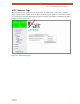

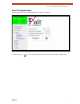


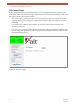
Table Of Contents
- EX-i Series GigE (FDD)
- Digital Microwave Radios
- Installation and Management Guide
- Legal Notice
- Open-Source License Information
- Table of Contents
- List of Figures
- List of Tables
- About this Document
- Introduction
- Pre-installation Tasks
- System Installation and Initiation Process
- Installation
- Configuration and Management
- Command Line Interface (CLI)
- Telnet into the Command Line Interface (CLI)
- Exalt Graphical User Interface (GUI)
- Quick Start
- Navigating the GUI
- Radio Information Page
- Administration Settings Page
- NTP and Time Zone Configurations
- Simple Network Management Protocol (SNMP) Configuration
- File Transfer Page
- File Activation Page
- System Configuration Page
- Allocation Page
- Ethernet Interface Configuration Page
- T1/E1 Configuration Pages
- MHS Configuration Page
- VLAN Configuration Page
- Ethernet Rate Limiting Page
- Ethernet Learning Page
- Syslog Configuration Page
- Ethernet Aggregation
- Cross Connect (X Connect) Page
- Alarms Page
- MHS Status Page
- Performance Page
- ATPC Statistics Page
- Event Log Page
- User Throughput Page
- Diagnostic Charts Page
- Ethernet Utilization Page
- PA Control Page
- Spectrum Analyzer
- Reboot Page
- Manual Page
- Specifications
- Interface Connections
- Troubleshooting
- Back-to-back Bench Testing
- General Compliance and Safety
- Safety Notices
- Regulatory Notices
- Regulatory Compliance
- EIRP Limits for the United States and Canada
- Licensing 6 and 11GHz Models
- Antennas 5GHz Models
- Copyright Notices
- END USER AGREEMENT
- Index

Exalt Installation and Management Guide
EX-i Series GigE (FDD) Digital Microwave Radios
82 202675-008
2016-06-01
PA Control Page
Radios configured with Power Amplifier (PA) protection switching automatically bypass the PA on
detected PA failures. The PA Control page provides ability for extended troubleshooting related to the
PA. Select from the following three options:
• Force Normal places the PA protection in its normal state where if issues are detected, the PA is
bypassed, dropping the transmit power approximately 10dB. In most link conditions, the link is
maintained.
• Force High forces a no PA bypass condition. If a PA issue is detected, this can help verify
improper performance.
• Force Low forces a PA bypass. This is useful for troubleshooting and initial link commissioning.
For link testing, this option ensures that the link has sufficient margin to maintain connection if PA
protection switching occurs.
Figure 56 PA Control page