
User's Manual
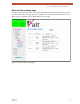


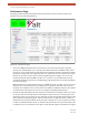
Table Of Contents
- EX-i Series GigE (FDD)
- Digital Microwave Radios
- Installation and Management Guide
- Legal Notice
- Open-Source License Information
- Table of Contents
- List of Figures
- List of Tables
- About this Document
- Introduction
- Pre-installation Tasks
- System Installation and Initiation Process
- Installation
- Configuration and Management
- Command Line Interface (CLI)
- Telnet into the Command Line Interface (CLI)
- Exalt Graphical User Interface (GUI)
- Quick Start
- Navigating the GUI
- Radio Information Page
- Administration Settings Page
- NTP and Time Zone Configurations
- Simple Network Management Protocol (SNMP) Configuration
- File Transfer Page
- File Activation Page
- System Configuration Page
- Allocation Page
- Ethernet Interface Configuration Page
- T1/E1 Configuration Pages
- MHS Configuration Page
- VLAN Configuration Page
- Ethernet Rate Limiting Page
- Ethernet Learning Page
- Syslog Configuration Page
- Ethernet Aggregation
- Cross Connect (X Connect) Page
- Alarms Page
- MHS Status Page
- Performance Page
- ATPC Statistics Page
- Event Log Page
- User Throughput Page
- Diagnostic Charts Page
- Ethernet Utilization Page
- PA Control Page
- Spectrum Analyzer
- Reboot Page
- Manual Page
- Specifications
- Interface Connections
- Troubleshooting
- Back-to-back Bench Testing
- General Compliance and Safety
- Safety Notices
- Regulatory Notices
- Regulatory Compliance
- EIRP Limits for the United States and Canada
- Licensing 6 and 11GHz Models
- Antennas 5GHz Models
- Copyright Notices
- END USER AGREEMENT
- Index

Exalt Installation and Management Guide
EX-i Series GigE (FDD) Digital Microwave Radios
202675-008 69
2016-06-01
The Temperature alarm monitors the internal temperature of the unit based on specific points inside
the radio chassis. It is normal for the internal temperature to be above the ambient temperature, so the
temperature reading may be higher than the highest specified ambient temperature. When the internal
electronics reach a point that is higher than the normal temperature rise at the highest ambient
temperature, the temperature alarm turns yellow. Power down the radio as soon as possible, and
investigate the cause of the temperature rise before the radio is put back into service. In almost all
cases, a temperature alarm is due to an external cause.
Additional alarm entries display for certain configurations, as listed in Table 6.
ATPC Indicates Automatic Transmit Power Control status:
• Green Solid = ATPC is enabled, but not active.
• Yellow Solid = ATPC is active.
• Grey = ATPC is disabled.
PA Protection Indicates the status of power amplifier protection:
• Green Solid = PA is OK; not in a maintenance state.
• Yellow Solid = PA is in a maintenance state (force high or force low, as set on the
PA
Control Page).
• Red Solid = PA has detected an issue.
Ethernet • Green Solid = Alarm enabled and Ethernet link present
• Red = Alarm enabled and Ethernet link not present
• Grey = Alarm disabled
DS3 Input • Green = Enabled and connection present (clocking confirmed)
• Red = Enabled and no connection present
• Yellow = Disabled and connection present
• Grey = Disabled or unavailable due to configuration
T1/E1 Input • Green = Enabled and connection present (clocking confirmed)
• Yellow = Disabled and connection present
• Red = Enabled and no connection present
• Grey = Disabled or unavailable due to configuration
Temperature • Green Solid = Normal temperature range
• Yellow Solid = Exceeding normal temperature range
Internal Fan Indicates the internal fan status. There are 3 fans for redundancy.
• Green = Fan OK
• Red = Fan in alarm
External Inputs (1 and 2) Indicates the status of the external alarm inputs from the ALARMS connector, in accordance
with the open/closed logic defined on the
System Configuration Page.
Link Security • Green = Security keys match
• Red = Security keys do not match
• Grey = Link is down
Table 5 Alarm status indicators (Continued)
Label Status