
User's Manual
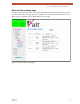
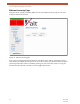

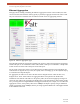


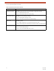
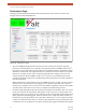
Table Of Contents
- EX-i Series GigE (FDD)
- Digital Microwave Radios
- Installation and Management Guide
- Legal Notice
- Open-Source License Information
- Table of Contents
- List of Figures
- List of Tables
- About this Document
- Introduction
- Pre-installation Tasks
- System Installation and Initiation Process
- Installation
- Configuration and Management
- Command Line Interface (CLI)
- Telnet into the Command Line Interface (CLI)
- Exalt Graphical User Interface (GUI)
- Quick Start
- Navigating the GUI
- Radio Information Page
- Administration Settings Page
- NTP and Time Zone Configurations
- Simple Network Management Protocol (SNMP) Configuration
- File Transfer Page
- File Activation Page
- System Configuration Page
- Allocation Page
- Ethernet Interface Configuration Page
- T1/E1 Configuration Pages
- MHS Configuration Page
- VLAN Configuration Page
- Ethernet Rate Limiting Page
- Ethernet Learning Page
- Syslog Configuration Page
- Ethernet Aggregation
- Cross Connect (X Connect) Page
- Alarms Page
- MHS Status Page
- Performance Page
- ATPC Statistics Page
- Event Log Page
- User Throughput Page
- Diagnostic Charts Page
- Ethernet Utilization Page
- PA Control Page
- Spectrum Analyzer
- Reboot Page
- Manual Page
- Specifications
- Interface Connections
- Troubleshooting
- Back-to-back Bench Testing
- General Compliance and Safety
- Safety Notices
- Regulatory Notices
- Regulatory Compliance
- EIRP Limits for the United States and Canada
- Licensing 6 and 11GHz Models
- Antennas 5GHz Models
- Copyright Notices
- END USER AGREEMENT
- Index

Exalt Installation and Management Guide
EX-i Series GigE (FDD) Digital Microwave Radios
68 202675-008
2016-06-01
Alarms Page
This page provides an easy-to-read summary of the alarm status of both local and remote radios. The
colors on this page reflect the color of the alarms displayed on the radio front panel. However,
additional detail displays on this page to aid in quick assessment of issues and status.
Figure 46 Alarms page
Table 5 lists alarm status conditions that appear on this page.
Table 5 Alarm status indicators
Label Status
Link System Indicates RF link status:
• Green Solid = Error-free connection (BER<10e-6)
• Yellow Solid = Errored connection (10e-3>BER >10e-6)
• Red Solid = No link (BER>10e-3)
RX Alarm When Rx RSL Differential is enabled, provides alarms for Space Diversity configurations.
• Green Solid = The Rx values of the two receivers are within 5dB of the programmed
differential value.
• Yellow Solid = The Rx values of the two receivers are further apart than 5dB of the
programmed differential value.