
User's Manual
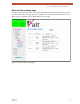
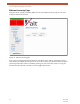

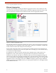


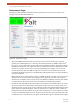
Table Of Contents
- EX-i Series GigE (FDD)
- Digital Microwave Radios
- Installation and Management Guide
- Legal Notice
- Open-Source License Information
- Table of Contents
- List of Figures
- List of Tables
- About this Document
- Introduction
- Pre-installation Tasks
- System Installation and Initiation Process
- Installation
- Configuration and Management
- Command Line Interface (CLI)
- Telnet into the Command Line Interface (CLI)
- Exalt Graphical User Interface (GUI)
- Quick Start
- Navigating the GUI
- Radio Information Page
- Administration Settings Page
- NTP and Time Zone Configurations
- Simple Network Management Protocol (SNMP) Configuration
- File Transfer Page
- File Activation Page
- System Configuration Page
- Allocation Page
- Ethernet Interface Configuration Page
- T1/E1 Configuration Pages
- MHS Configuration Page
- VLAN Configuration Page
- Ethernet Rate Limiting Page
- Ethernet Learning Page
- Syslog Configuration Page
- Ethernet Aggregation
- Cross Connect (X Connect) Page
- Alarms Page
- MHS Status Page
- Performance Page
- ATPC Statistics Page
- Event Log Page
- User Throughput Page
- Diagnostic Charts Page
- Ethernet Utilization Page
- PA Control Page
- Spectrum Analyzer
- Reboot Page
- Manual Page
- Specifications
- Interface Connections
- Troubleshooting
- Back-to-back Bench Testing
- General Compliance and Safety
- Safety Notices
- Regulatory Notices
- Regulatory Compliance
- EIRP Limits for the United States and Canada
- Licensing 6 and 11GHz Models
- Antennas 5GHz Models
- Copyright Notices
- END USER AGREEMENT
- Index

Exalt Installation and Management Guide
EX-i Series GigE (FDD) Digital Microwave Radios
66 202675-008
2016-06-01
Ethernet Aggregation
This page allows enabling or disabling the Ethernet Aggregation function. When enabled, the radio
can be interconnected with other radios (typically in parallel) to aggregate the Ethernet traffic so that
only one connection is needed at each end without external routers or aggregating switches.
Figure 44 Ethernet Aggregation page
The radio that has Ethernet Aggregation enabled is the ‘primary’ radio in the aggregation arrangement,
and the EXP port can be connected to another radio’s EXP or GbE port or connected to a simple GbE
switch connected to other radio’s EXP ports and/or GbE ports.
The net result of this feature is that a set of radios appear as ONE connection to the LAN/WAN. If a
radio link fails or degrades for any reason, the capacity scales accordingly, up or down dynamically up
to a maximum of 1Gbps full-duplex.
For aggregation, all radios at one side of the link must be designated ‘East’ and at the other end,
designate all as ‘West.’ Each radio has an Aggregator ID that corresponds to the ‘Radio Link’
information at the bottom of the table. For the primary radio, the relative throughput percentages are
entered for each radio in the aggregation set. Radio Link 1 is the radio itself. For links running ACM,
use a percentage based on target modulation throughput (maximum). For example, in a two-radio link
aggregation scenario, if the primary radio carries 300Mbps full-duplex capacity at target modulation
and the second radio carries 200Mbps, then the percentage applied to Radio Link 1 Throughput should
be 60 and Radio Link 2 40.