
User's Manual


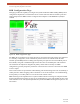


Table Of Contents
- EX-i Series GigE (FDD)
- Digital Microwave Radios
- Installation and Management Guide
- Legal Notice
- Open-Source License Information
- Table of Contents
- List of Figures
- List of Tables
- About this Document
- Introduction
- Pre-installation Tasks
- System Installation and Initiation Process
- Installation
- Configuration and Management
- Command Line Interface (CLI)
- Telnet into the Command Line Interface (CLI)
- Exalt Graphical User Interface (GUI)
- Quick Start
- Navigating the GUI
- Radio Information Page
- Administration Settings Page
- NTP and Time Zone Configurations
- Simple Network Management Protocol (SNMP) Configuration
- File Transfer Page
- File Activation Page
- System Configuration Page
- Allocation Page
- Ethernet Interface Configuration Page
- T1/E1 Configuration Pages
- MHS Configuration Page
- VLAN Configuration Page
- Ethernet Rate Limiting Page
- Ethernet Learning Page
- Syslog Configuration Page
- Ethernet Aggregation
- Cross Connect (X Connect) Page
- Alarms Page
- MHS Status Page
- Performance Page
- ATPC Statistics Page
- Event Log Page
- User Throughput Page
- Diagnostic Charts Page
- Ethernet Utilization Page
- PA Control Page
- Spectrum Analyzer
- Reboot Page
- Manual Page
- Specifications
- Interface Connections
- Troubleshooting
- Back-to-back Bench Testing
- General Compliance and Safety
- Safety Notices
- Regulatory Notices
- Regulatory Compliance
- EIRP Limits for the United States and Canada
- Licensing 6 and 11GHz Models
- Antennas 5GHz Models
- Copyright Notices
- END USER AGREEMENT
- Index

Exalt Installation and Management Guide
EX-i Series GigE (FDD) Digital Microwave Radios
60 202675-008
2016-06-01
MHS Configuration Page
This page provides the capability to configure the system for Monitored Hot Standby (MHS). These
configurations implement a second terminal at one or both ends of the link for hardware protection
and/or path protection. MHS cannot be configured when Adaptive Coded Modulation (ACM) is
enabled.
Figure 39 MHS Configuration page
For MHS, the two terminals at one end of the link are connected to the same antenna. One terminal is
in a ‘standby’ configuration, and is automatically selected if issues are identified with the other
terminal. Special MHS protection cabling (sold separately) is required to connect the PROT ports of
the terminals, along with a standard straight-wired CAT5 cable for the EXP ports of the terminals.
One terminal at the endpoint is designated as primary and the other secondary. For MHS
configurations, generally the primary terminal is connected to the on the lower-loss side of the MHS
receiver coupler.
The Lock On features are provided for troubleshooting. The default setting is No Lock on (Normal), to
enable protection. When swapping cables or hardware on one of the terminals or for troubleshooting,
set the primary or secondary radio to Lock On and set the amount of time.
MHS switching can be implemented in a ‘hybrid’ fashion instead of selecting one complete terminal.
In this configuration the interface circuitry of one terminal may be in use, while the RF circuitry of the
other terminal is in use. This hybrid implementation yields faster MHS switching and requires no user
intervention.