
User's Manual


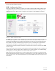


Table Of Contents
- EX-i Series GigE (FDD)
- Digital Microwave Radios
- Installation and Management Guide
- Legal Notice
- Open-Source License Information
- Table of Contents
- List of Figures
- List of Tables
- About this Document
- Introduction
- Pre-installation Tasks
- System Installation and Initiation Process
- Installation
- Configuration and Management
- Command Line Interface (CLI)
- Telnet into the Command Line Interface (CLI)
- Exalt Graphical User Interface (GUI)
- Quick Start
- Navigating the GUI
- Radio Information Page
- Administration Settings Page
- NTP and Time Zone Configurations
- Simple Network Management Protocol (SNMP) Configuration
- File Transfer Page
- File Activation Page
- System Configuration Page
- Allocation Page
- Ethernet Interface Configuration Page
- T1/E1 Configuration Pages
- MHS Configuration Page
- VLAN Configuration Page
- Ethernet Rate Limiting Page
- Ethernet Learning Page
- Syslog Configuration Page
- Ethernet Aggregation
- Cross Connect (X Connect) Page
- Alarms Page
- MHS Status Page
- Performance Page
- ATPC Statistics Page
- Event Log Page
- User Throughput Page
- Diagnostic Charts Page
- Ethernet Utilization Page
- PA Control Page
- Spectrum Analyzer
- Reboot Page
- Manual Page
- Specifications
- Interface Connections
- Troubleshooting
- Back-to-back Bench Testing
- General Compliance and Safety
- Safety Notices
- Regulatory Notices
- Regulatory Compliance
- EIRP Limits for the United States and Canada
- Licensing 6 and 11GHz Models
- Antennas 5GHz Models
- Copyright Notices
- END USER AGREEMENT
- Index

Exalt Installation and Management Guide
EX-i Series GigE (FDD) Digital Microwave Radios
202675-008 55
2016-06-01
Figure 33 T1 Interface Configuration page
E1, DS3, and OC3 Configuration Pages
For all other TDM configurations (E1, DS3, and OC3), configuration is nearly identical to the T1
configuration. However, the LBO and AIS settings must match the interface standard. For some DS3
interface units, additional configuration is provided to select the ground configurations of the DS3
ports (grounded or not grounded).
When setting Alarms, review the Allocation and X-Connect settings relative to how many and which
specific ports will be active for different ACM states. See the
T1 Interface Configuration Page section
for advice on alarm settings.
E1 Interface Configuration Page
This page (Figure 34) allows the administrator to enable/disable each individual E1 channel.The AIS
can also be enabled and disabled for each input. If enabled, the radio places an AIS code on the output
of the associated interface if and when the link fails or when there is no E1 signal available from the far
end to provide the user at the local end. Loopback controls are also provided (see T1/E1 Loopback).