
User's Manual

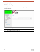

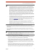


Table Of Contents
- EX-i Series GigE (FDD)
- Digital Microwave Radios
- Installation and Management Guide
- Legal Notice
- Open-Source License Information
- Table of Contents
- List of Figures
- List of Tables
- About this Document
- Introduction
- Pre-installation Tasks
- System Installation and Initiation Process
- Installation
- Configuration and Management
- Command Line Interface (CLI)
- Telnet into the Command Line Interface (CLI)
- Exalt Graphical User Interface (GUI)
- Quick Start
- Navigating the GUI
- Radio Information Page
- Administration Settings Page
- NTP and Time Zone Configurations
- Simple Network Management Protocol (SNMP) Configuration
- File Transfer Page
- File Activation Page
- System Configuration Page
- Allocation Page
- Ethernet Interface Configuration Page
- T1/E1 Configuration Pages
- MHS Configuration Page
- VLAN Configuration Page
- Ethernet Rate Limiting Page
- Ethernet Learning Page
- Syslog Configuration Page
- Ethernet Aggregation
- Cross Connect (X Connect) Page
- Alarms Page
- MHS Status Page
- Performance Page
- ATPC Statistics Page
- Event Log Page
- User Throughput Page
- Diagnostic Charts Page
- Ethernet Utilization Page
- PA Control Page
- Spectrum Analyzer
- Reboot Page
- Manual Page
- Specifications
- Interface Connections
- Troubleshooting
- Back-to-back Bench Testing
- General Compliance and Safety
- Safety Notices
- Regulatory Notices
- Regulatory Compliance
- EIRP Limits for the United States and Canada
- Licensing 6 and 11GHz Models
- Antennas 5GHz Models
- Copyright Notices
- END USER AGREEMENT
- Index

Exalt Installation and Management Guide
EX-i Series GigE (FDD) Digital Microwave Radios
202675-008 51
2016-06-01
Allocation Page
This page allows the administrator to determine how the TDM interfaces (T1, E1, DS3, OC3, etc.) and
remaining Ethernet capacity are allocated when ACM is enabled. Since ACM changes the capacity of
the radio, it is critical to determine how those changes impact the traffic carried over the link.
Figure 31 Allocation page
The left side of the chart shows the different modulations available for ACM. Columns display under
different TDM type column headings (such as DS3 and T1 shown). Selection of how many of each
interface is determined by the selections for each modulation.
The bar graph color codes allocation of the TDM interfaces, showing each interface and the relative
capacity it is occupying. Orange indicates remaining Ethernet capacity for that modulation.
At the right of the graph, the full-duplex Ethernet capacity displays in Mbps. The total full-duplex
capacity displays in the System column.
It may be necessary to configure the TDM interfaces. A link displays under the graph to ease
configuring any TDM interface.
Note: The allocation of TDM interfaces only defines HOW MANY channels are allocated; it
does not define WHICH physical ports are allocated. Priority of port assignments is
controlled on the
Cross Connect (X Connect) Page. If a TDM allocation change occurs
between modulations, the priority defined in Cross-Connect determines which ports are
added or dropped.