
User's Manual

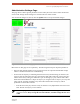

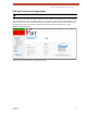


Table Of Contents
- EX-i Series GigE (FDD)
- Digital Microwave Radios
- Installation and Management Guide
- Legal Notice
- Open-Source License Information
- Table of Contents
- List of Figures
- List of Tables
- About this Document
- Introduction
- Pre-installation Tasks
- System Installation and Initiation Process
- Installation
- Configuration and Management
- Command Line Interface (CLI)
- Telnet into the Command Line Interface (CLI)
- Exalt Graphical User Interface (GUI)
- Quick Start
- Navigating the GUI
- Radio Information Page
- Administration Settings Page
- NTP and Time Zone Configurations
- Simple Network Management Protocol (SNMP) Configuration
- File Transfer Page
- File Activation Page
- System Configuration Page
- Allocation Page
- Ethernet Interface Configuration Page
- T1/E1 Configuration Pages
- MHS Configuration Page
- VLAN Configuration Page
- Ethernet Rate Limiting Page
- Ethernet Learning Page
- Syslog Configuration Page
- Ethernet Aggregation
- Cross Connect (X Connect) Page
- Alarms Page
- MHS Status Page
- Performance Page
- ATPC Statistics Page
- Event Log Page
- User Throughput Page
- Diagnostic Charts Page
- Ethernet Utilization Page
- PA Control Page
- Spectrum Analyzer
- Reboot Page
- Manual Page
- Specifications
- Interface Connections
- Troubleshooting
- Back-to-back Bench Testing
- General Compliance and Safety
- Safety Notices
- Regulatory Notices
- Regulatory Compliance
- EIRP Limits for the United States and Canada
- Licensing 6 and 11GHz Models
- Antennas 5GHz Models
- Copyright Notices
- END USER AGREEMENT
- Index

Exalt Installation and Management Guide
EX-i Series GigE (FDD) Digital Microwave Radios
202675-008 37
2016-06-01
Administration Settings Page
This page allows contains general parameters for the radio system. The Current Value column lists
entries actual settings. Desired changes are entered in the New Value column.
After all desired changes are entered, click the Update button to accept and enable changes.
Figure 23 Administration Settings page
Most entries on this page are self-explanatory. The following lists unique or important parameters.
• Fill in the date and time fields as soon as practical. Events are captured with time/date stamps,
which is valuable information for troubleshooting.
• Set the Link Security Key to something other than the factory default setting (12 characters, all
zeros) at each end. The link security key must match at both sides of the link. If the security key
remains at the factory setting, the radio link is open to sabotage by a party with the same radio
model. Each link should have a unique security key. If using the same security key for every link
in the network, the radio could link to any other radio with the same security key. This is
problematic in multi-radio networks.
– Note that the security key must be exactly 12 characters. Any alphanumeric character can be
used. The link security key is case sensitive.
Note: Changing the link security key interrupts transmission until the opposite end is
changed to match. Always change the far-end radio first, and then change the near-end
radio.