
User's Manual
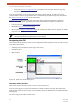
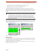


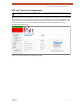


Table Of Contents
- EX-i Series GigE (FDD)
- Digital Microwave Radios
- Installation and Management Guide
- Legal Notice
- Open-Source License Information
- Table of Contents
- List of Figures
- List of Tables
- About this Document
- Introduction
- Pre-installation Tasks
- System Installation and Initiation Process
- Installation
- Configuration and Management
- Command Line Interface (CLI)
- Telnet into the Command Line Interface (CLI)
- Exalt Graphical User Interface (GUI)
- Quick Start
- Navigating the GUI
- Radio Information Page
- Administration Settings Page
- NTP and Time Zone Configurations
- Simple Network Management Protocol (SNMP) Configuration
- File Transfer Page
- File Activation Page
- System Configuration Page
- Allocation Page
- Ethernet Interface Configuration Page
- T1/E1 Configuration Pages
- MHS Configuration Page
- VLAN Configuration Page
- Ethernet Rate Limiting Page
- Ethernet Learning Page
- Syslog Configuration Page
- Ethernet Aggregation
- Cross Connect (X Connect) Page
- Alarms Page
- MHS Status Page
- Performance Page
- ATPC Statistics Page
- Event Log Page
- User Throughput Page
- Diagnostic Charts Page
- Ethernet Utilization Page
- PA Control Page
- Spectrum Analyzer
- Reboot Page
- Manual Page
- Specifications
- Interface Connections
- Troubleshooting
- Back-to-back Bench Testing
- General Compliance and Safety
- Safety Notices
- Regulatory Notices
- Regulatory Compliance
- EIRP Limits for the United States and Canada
- Licensing 6 and 11GHz Models
- Antennas 5GHz Models
- Copyright Notices
- END USER AGREEMENT
- Index

Exalt Installation and Management Guide
EX-i Series GigE (FDD) Digital Microwave Radios
202675-008 35
2016-06-01
• Green indicates the system is communicating and all functions are normal
• Yellow indicates a minor non-traffic affecting alarm condition
• Red indicates a major traffic affecting alarm condition
The left panel summarizes the alarm conditions of the local radio (the radio that matches the IP
address). The information displayed is the IP address and the endpoint identifier (Radio A or Radio B).
The right panel summarizes the alarm conditions of the remote radio (the radio linked to the local
radio).
The Summary Status Section allows the Exalt GUI to be a rudimentary management system. Minimize
the browser window to display just the top bar or the top bar and radio information, and open several
browsers on the desktop. When a window status changes to yellow or red, you can quickly maximize
that window to determine the issues.
Figure 21 Summary status information
Navigation Panel
In the navigation panel, pages with sub-pages have a plus (+) to the left of the page link. Click the plus
sign or page name title to view sub-page titles. The pages can be collapsed to hide the sub-pages when
a minus (–) sign appears to the left of the page link.
Management pages are indicated with an X to the left of the page name. Click the X or page name to
display the page within the main window.
Note: The ‘local’ radio might be the near-end or the far-end radio, depending on the
management interface connection. The terms local and remote refer to the orientation of the
radio terminals relative to the IP address you are managing. When making certain changes to
a near-end radio without first making changes to the far-end radio, the link may become
disconnected unless configuration changes are reverted to their original settings. When
making changes that may disrupt the link, always change the far-end radio first, and then
the near-end radio to match.