
User's Manual


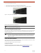


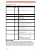


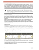
Table Of Contents
- EX-i Series GigE (FDD)
- Digital Microwave Radios
- Installation and Management Guide
- Legal Notice
- Open-Source License Information
- Table of Contents
- List of Figures
- List of Tables
- About this Document
- Introduction
- Pre-installation Tasks
- System Installation and Initiation Process
- Installation
- Configuration and Management
- Command Line Interface (CLI)
- Telnet into the Command Line Interface (CLI)
- Exalt Graphical User Interface (GUI)
- Quick Start
- Navigating the GUI
- Radio Information Page
- Administration Settings Page
- NTP and Time Zone Configurations
- Simple Network Management Protocol (SNMP) Configuration
- File Transfer Page
- File Activation Page
- System Configuration Page
- Allocation Page
- Ethernet Interface Configuration Page
- T1/E1 Configuration Pages
- MHS Configuration Page
- VLAN Configuration Page
- Ethernet Rate Limiting Page
- Ethernet Learning Page
- Syslog Configuration Page
- Ethernet Aggregation
- Cross Connect (X Connect) Page
- Alarms Page
- MHS Status Page
- Performance Page
- ATPC Statistics Page
- Event Log Page
- User Throughput Page
- Diagnostic Charts Page
- Ethernet Utilization Page
- PA Control Page
- Spectrum Analyzer
- Reboot Page
- Manual Page
- Specifications
- Interface Connections
- Troubleshooting
- Back-to-back Bench Testing
- General Compliance and Safety
- Safety Notices
- Regulatory Notices
- Regulatory Compliance
- EIRP Limits for the United States and Canada
- Licensing 6 and 11GHz Models
- Antennas 5GHz Models
- Copyright Notices
- END USER AGREEMENT
- Index

Exalt Installation and Management Guide
EX-i Series GigE (FDD) Digital Microwave Radios
202675-008 21
2016-06-01
In most configurations, the diplexers used for two ends of a link are the same diplexer, but mounted in
opposite physical orientation (rotated 180 degrees relative to one another), as shown in Figure 13.
Figure 13 Diplexer orientation for a typical 'link' of radios
Note in Figure 13, that this is the same diplexer for both radios, but they are mounted upside down
relative to one another. It is a logical arrangement because one radio is configured to transmit across
the same range of frequency that the opposite radio is configured to receive and vice-versa.
Non-Standard Frequency Pairs
From time to time, a licensing authority may assign a radio to be used on frequency pairs not
accommodated by Exalt standard diplexers. In these cases, there can be two separate filters and a
Notes:
1 The radio must have the software configured to match the ID number (orientation) of the
diplexer, as shown in the right-side-up text at the top center of the diplexer. See
System
Configuration Page for details. On the GUI page, there is a Diplexer ID selection. This
must match what is printed right-side-up on the installed diplexer. Once properly
configured, the radio can tune to center frequencies and bandwidths accommodated by
this diplexer, as mounted.
2 Two semi-rigid coaxial cables are provided with each diplexer. These must be connected
to the TX and RX1 rear-panel ports of the radio, as shown in Figure 12 and Figure 13.
3 The frequency range shown on the diplexer label indicate the EDGE frequency range of
the diplexer, not the center tuning range. The center tuning range is determined by the
Occupied Bandwidth setting of the radio, and is 1/2 of the Bandwidth value (in MHz) in
from the edges of the diplexer.
NOTE TX AND RX FREQUENCIES MATCH AT EITHER END