
User's Manual


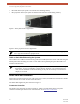


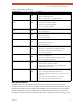


Table Of Contents
- EX-i Series GigE (FDD)
- Digital Microwave Radios
- Installation and Management Guide
- Legal Notice
- Open-Source License Information
- Table of Contents
- List of Figures
- List of Tables
- About this Document
- Introduction
- Pre-installation Tasks
- System Installation and Initiation Process
- Installation
- Configuration and Management
- Command Line Interface (CLI)
- Telnet into the Command Line Interface (CLI)
- Exalt Graphical User Interface (GUI)
- Quick Start
- Navigating the GUI
- Radio Information Page
- Administration Settings Page
- NTP and Time Zone Configurations
- Simple Network Management Protocol (SNMP) Configuration
- File Transfer Page
- File Activation Page
- System Configuration Page
- Allocation Page
- Ethernet Interface Configuration Page
- T1/E1 Configuration Pages
- MHS Configuration Page
- VLAN Configuration Page
- Ethernet Rate Limiting Page
- Ethernet Learning Page
- Syslog Configuration Page
- Ethernet Aggregation
- Cross Connect (X Connect) Page
- Alarms Page
- MHS Status Page
- Performance Page
- ATPC Statistics Page
- Event Log Page
- User Throughput Page
- Diagnostic Charts Page
- Ethernet Utilization Page
- PA Control Page
- Spectrum Analyzer
- Reboot Page
- Manual Page
- Specifications
- Interface Connections
- Troubleshooting
- Back-to-back Bench Testing
- General Compliance and Safety
- Safety Notices
- Regulatory Notices
- Regulatory Compliance
- EIRP Limits for the United States and Canada
- Licensing 6 and 11GHz Models
- Antennas 5GHz Models
- Copyright Notices
- END USER AGREEMENT
- Index

Exalt Installation and Management Guide
EX-i Series GigE (FDD) Digital Microwave Radios
202675-008 19
2016-06-01
RMT (Remote) Button
The RMT button is the only external control on the radios. This button allows easy and quick
evaluation of the status of the remote-end radio. When the RMT LED is amber flashes, this is an alert
that the remote end has an alarm condition. Press the RMT button to determine the alarm conditions.
When the RMT button is pressed and held and local LEDs flash, this indicates that no remote-end
information is available. This indicates that the remote radio is either not powered, is booting, or is not
PROT Right Corner Green
LED
Indicates MHS protection communication status:
• Solid = Communications OK
• Off = Communications error or MHS disabled
ETHERNET ETH1/2 Left
Corner
Green
LED
• Solid = Negotiated @ 1000Mbps
• Fast Flash = Negotiated @ 100Mbps
• Slow Flash = Negotiated @ 10Mbps
• Off = No connection negotiated
ETHERNET ETH1/2 Right
Corner
Green
LED
• Solid/Flashing = Data present
• Off = No data present
SFP Left Side Green
LED
SFP link status:
• Solid = Link engaged
• Off = Link not engaged
SFP Right Side Green
LED
SFP traffic:
• Solid/Flashing = Data present
• Off = No data present
T1/E1 Left Corner Green
LED
• Solid = Connection present (clocking confirmed)
• Fast Flash = Connection present; coding/clock problem
• Slow Flash = Connection present, but unexpected
• Off = No connection/clock
T1/E1 Right Corner Green
LED
• Solid = In a loopback state
• Fast Flash = Automatic indication signal (AIS) is active
• Off = No loopback; no AIS activity
RMT (LED inside button) Amber
LED
• Off = Remote end LINK and STATUS LEDs are both green
• Solid = No remote end status available
• Flash = Alarm conditions at the remote end (LINK and/or
STATUS LEDs are non-green)
(Unmarked LED on rear panel) 2-color
LED
Indicates overall status (from the rear panel):
• Green = LINK and STATUS LEDs are both green
• Red Flash = LINK and/or STATUS are in a yellow state; no red
states exist
• Red Solid = LINK and/or STATUS are in a red state
• Off = Improperly powered or fatal system failure
Table 3 LED indicators (Continued)
Location/Label Type Function