
User's Manual


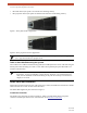


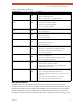


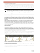
Table Of Contents
- EX-i Series GigE (FDD)
- Digital Microwave Radios
- Installation and Management Guide
- Legal Notice
- Open-Source License Information
- Table of Contents
- List of Figures
- List of Tables
- About this Document
- Introduction
- Pre-installation Tasks
- System Installation and Initiation Process
- Installation
- Configuration and Management
- Command Line Interface (CLI)
- Telnet into the Command Line Interface (CLI)
- Exalt Graphical User Interface (GUI)
- Quick Start
- Navigating the GUI
- Radio Information Page
- Administration Settings Page
- NTP and Time Zone Configurations
- Simple Network Management Protocol (SNMP) Configuration
- File Transfer Page
- File Activation Page
- System Configuration Page
- Allocation Page
- Ethernet Interface Configuration Page
- T1/E1 Configuration Pages
- MHS Configuration Page
- VLAN Configuration Page
- Ethernet Rate Limiting Page
- Ethernet Learning Page
- Syslog Configuration Page
- Ethernet Aggregation
- Cross Connect (X Connect) Page
- Alarms Page
- MHS Status Page
- Performance Page
- ATPC Statistics Page
- Event Log Page
- User Throughput Page
- Diagnostic Charts Page
- Ethernet Utilization Page
- PA Control Page
- Spectrum Analyzer
- Reboot Page
- Manual Page
- Specifications
- Interface Connections
- Troubleshooting
- Back-to-back Bench Testing
- General Compliance and Safety
- Safety Notices
- Regulatory Notices
- Regulatory Compliance
- EIRP Limits for the United States and Canada
- Licensing 6 and 11GHz Models
- Antennas 5GHz Models
- Copyright Notices
- END USER AGREEMENT
- Index

Exalt Installation and Management Guide
EX-i Series GigE (FDD) Digital Microwave Radios
18 202675-008
2016-06-01
Figure 10 DS3 connectors and grounding switches
For some models, DS3 IN and DS3 OUT connections (Figure 10) can be independently grounded or
ungrounded to the chassis using a small DIP switch between the connectors. Ground loops to
connected equipment must be avoided. Set the DIP switches accordingly.
LED Indicators
Table 3 provides details of the LED indicators on theEX-i Series GigE (FDD) radios. See Alarms Page
for information on how the Exalt GUI displays LED status.
Table 3 LED indicators
Location/Label Type Function
LINK 3-color
LED
Indicates RF link status:
• Green Solid = Error-free connection (BER<10e-6)
• Yellow Solid = Errored connection (10e-3>BER >10e-6)
• Red Solid = No link (BER>10e-3)
• Red Flash= No remote information available (when RMT is
pressed and held)
• Off = Improperly powered or fatal system failure
STATUS 3-color
LED
Indicates system status:
• Green Solid = No alarm conditions (normal operation)
• Yellow Solid = Alarm conditions, not traffic effecting
• Yellow Slow Flash = In loopback (from this end)
• Yellow Fast Flash = In loopback (at this end)
• Red Solid = Alarm conditions; traffic effecting
• Red Flash = No remote information available (when RMT is
pressed and held)
• Off = Improperly powered or fatal system failure
DS3 3-color
LED
Indicates DS3 connection status:
• Green Solid = No alarm conditions (normal operation)
• Yellow Solid = DS3 signal present, but DS3 is not enabled
• Red Solid = DS3 enabled, but not present
• Off = DS3 not in use
PROT Left Corner Green
LED
Indicates primary/secondary state for MHS protection:
• Solid = Configured as primary
• Off = Configured as secondary or MHS disabled