
User's Manual


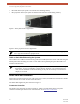


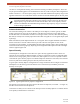
Table Of Contents
- EX-i Series GigE (FDD)
- Digital Microwave Radios
- Installation and Management Guide
- Legal Notice
- Open-Source License Information
- Table of Contents
- List of Figures
- List of Tables
- About this Document
- Introduction
- Pre-installation Tasks
- System Installation and Initiation Process
- Installation
- Configuration and Management
- Command Line Interface (CLI)
- Telnet into the Command Line Interface (CLI)
- Exalt Graphical User Interface (GUI)
- Quick Start
- Navigating the GUI
- Radio Information Page
- Administration Settings Page
- NTP and Time Zone Configurations
- Simple Network Management Protocol (SNMP) Configuration
- File Transfer Page
- File Activation Page
- System Configuration Page
- Allocation Page
- Ethernet Interface Configuration Page
- T1/E1 Configuration Pages
- MHS Configuration Page
- VLAN Configuration Page
- Ethernet Rate Limiting Page
- Ethernet Learning Page
- Syslog Configuration Page
- Ethernet Aggregation
- Cross Connect (X Connect) Page
- Alarms Page
- MHS Status Page
- Performance Page
- ATPC Statistics Page
- Event Log Page
- User Throughput Page
- Diagnostic Charts Page
- Ethernet Utilization Page
- PA Control Page
- Spectrum Analyzer
- Reboot Page
- Manual Page
- Specifications
- Interface Connections
- Troubleshooting
- Back-to-back Bench Testing
- General Compliance and Safety
- Safety Notices
- Regulatory Notices
- Regulatory Compliance
- EIRP Limits for the United States and Canada
- Licensing 6 and 11GHz Models
- Antennas 5GHz Models
- Copyright Notices
- END USER AGREEMENT
- Index

Exalt Installation and Management Guide
EX-i Series GigE (FDD) Digital Microwave Radios
202675-008 15
2016-06-01
Installation
This section presents all tasks required to install the Exalt Digital Microwave Radio.
Mechanical Configuration and Mounting
TheEX-i Series GigE (FDD) radios are one-piece designs intended for deployment in a telecom
equipment rack indoors or in an appropriate environmental enclosure. The device must be deployed
within an ambient temperature range as specified, and properly ventilated with no obstructions to the
air intake and exhaust. The terminal occupies 2 rack units (2RUs = 3.5"/9cm) height in a typical
telecom rack.
In most cases, additional racked equipment can be placed directly above and/or below the device with
no empty spaces in the rack. However, depending on power consumption and ventilation for adjoining
devices, they may pass heat to the device, not allowing the radio to cool properly and increasing the
risk of malfunction. Heat dissipation from the radio may also affect adjoining devices. Provide air
space above and below the device, where possible. If not possible, a thermal analysis may be required
by a professional engineer to determine the impact of thermal transfer between all adjoining units.
Provide proper clearance for all cables and connectors attached to the device. All RF connectors,
cables, and adapters must be rated for operation within the radio’s frequency range. RF connector
losses must be accounted for within the link engineering design and output power settings.
Rack Mounting
Rack mounting hardware for a standard 19" (48cm) rack is included in the accessory kit. Attach the
rack mounting brackets to the sides of the unit with the provided screws. The radio can be mounted in
one of four configurations:
• Front flush mount (front panel even with the rack mounting surface)
Figure 5 Front flush mount configuration
• Front projection mount (front panel extended forward from the rack mounting surface)
Figure 6 Front projection mount configuration