
User's Manual
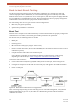


Table Of Contents
- EX-i Series GigE (FDD)
- Digital Microwave Radios
- Installation and Management Guide
- Legal Notice
- Open-Source License Information
- Table of Contents
- List of Figures
- List of Tables
- About this Document
- Introduction
- Pre-installation Tasks
- System Installation and Initiation Process
- Installation
- Configuration and Management
- Command Line Interface (CLI)
- Telnet into the Command Line Interface (CLI)
- Exalt Graphical User Interface (GUI)
- Quick Start
- Navigating the GUI
- Radio Information Page
- Administration Settings Page
- NTP and Time Zone Configurations
- Simple Network Management Protocol (SNMP) Configuration
- File Transfer Page
- File Activation Page
- System Configuration Page
- Allocation Page
- Ethernet Interface Configuration Page
- T1/E1 Configuration Pages
- MHS Configuration Page
- VLAN Configuration Page
- Ethernet Rate Limiting Page
- Ethernet Learning Page
- Syslog Configuration Page
- Ethernet Aggregation
- Cross Connect (X Connect) Page
- Alarms Page
- MHS Status Page
- Performance Page
- ATPC Statistics Page
- Event Log Page
- User Throughput Page
- Diagnostic Charts Page
- Ethernet Utilization Page
- PA Control Page
- Spectrum Analyzer
- Reboot Page
- Manual Page
- Specifications
- Interface Connections
- Troubleshooting
- Back-to-back Bench Testing
- General Compliance and Safety
- Safety Notices
- Regulatory Notices
- Regulatory Compliance
- EIRP Limits for the United States and Canada
- Licensing 6 and 11GHz Models
- Antennas 5GHz Models
- Copyright Notices
- END USER AGREEMENT
- Index

Exalt Installation and Management Guide
EX-i Series GigE (FDD) Digital Microwave Radios
112 202675-008
2016-06-01
EIRP Limits for the United States and Canada
5725–5850 MHz Band
For 5GHz EX-i Series GigE models within the 5725–5850 MHz band, the maximum EIRP allowed is
67.9 dBm. The maximum output power of the radio is +30dBm in all modulations.
P = 67.9 – G + L
where:
Note: The professional installer is responsible to ensure that RF output power is properly
adjusted to not exceed regulatory limits.
P = Maximum transmitter output power of radio, in dBm.
G = Specified gain of antenna, in dBi, from 5725 to 5850 MHz.
L = Total transmission system losses of all elements between the radio’s RF connector and
the antenna’s RF connector (all cables, connectors, lightning suppressors), in dB, as
specified or measured between 5725 and 5850 MHz.