
User's Manual
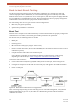


Table Of Contents
- EX-i Series GigE (FDD)
- Digital Microwave Radios
- Installation and Management Guide
- Legal Notice
- Open-Source License Information
- Table of Contents
- List of Figures
- List of Tables
- About this Document
- Introduction
- Pre-installation Tasks
- System Installation and Initiation Process
- Installation
- Configuration and Management
- Command Line Interface (CLI)
- Telnet into the Command Line Interface (CLI)
- Exalt Graphical User Interface (GUI)
- Quick Start
- Navigating the GUI
- Radio Information Page
- Administration Settings Page
- NTP and Time Zone Configurations
- Simple Network Management Protocol (SNMP) Configuration
- File Transfer Page
- File Activation Page
- System Configuration Page
- Allocation Page
- Ethernet Interface Configuration Page
- T1/E1 Configuration Pages
- MHS Configuration Page
- VLAN Configuration Page
- Ethernet Rate Limiting Page
- Ethernet Learning Page
- Syslog Configuration Page
- Ethernet Aggregation
- Cross Connect (X Connect) Page
- Alarms Page
- MHS Status Page
- Performance Page
- ATPC Statistics Page
- Event Log Page
- User Throughput Page
- Diagnostic Charts Page
- Ethernet Utilization Page
- PA Control Page
- Spectrum Analyzer
- Reboot Page
- Manual Page
- Specifications
- Interface Connections
- Troubleshooting
- Back-to-back Bench Testing
- General Compliance and Safety
- Safety Notices
- Regulatory Notices
- Regulatory Compliance
- EIRP Limits for the United States and Canada
- Licensing 6 and 11GHz Models
- Antennas 5GHz Models
- Copyright Notices
- END USER AGREEMENT
- Index

Exalt Installation and Management Guide
EX-i Series GigE (FDD) Digital Microwave Radios
202675-008 105
2016-06-01
It can be beneficial to have a computer to verify configuration in case of red LEDs or to pre-configure
the radio as desired for operation. Follow the instructions in
Configuration and Management.
Specification Performance Verification
The specification performance verification is a more detailed test that allows you to verify that the
radio’s output power and threshold specifications are being met. This is typically a test that would only
be performed in a troubleshooting scenario, but can be performed before installation to provide a
detailed record or ensure radio performance before installation.
This test is identical to the basic test, but in place of the fixed attenuation, it requires the use of
calibrated variable attenuation, or a set of calibrated fixed attenuators, or a combination of both, adding
to a total attenuation value of 120dB, as measured at the operating frequency of the radio. In addition,
a volt meter or computer is also required.
Connect the system as shown in Figure 66, using the combination of fixed and variable attenuation
between the radio’s RF ports. Connect the volt meter to either radio’s RSL test point and associated
reference ground connection.
In this test, it is desirable to use pre-tested RF cables, known to be good, and the insertion loss is
known at the operating frequency. If the cables are short (6'/2m or less), you can estimate the loss,
including connectors, to be less than 1dB each. The estimate of cable loss is critical to the overall
confidence of the measurements made in this test.
There are two critical specifications that can be tested in this configuration:
• RF output power
• Radio receiver threshold
To measure transmitter output power, simply insert any value of attenuation between the radios
between 60 and 90dB. Ensure that both RF output power settings are at maximum. Use the volt meter
to measure RSL in both directions. The RSL measured value should match the appropriate value
according to the inserted attenuation, such as:
RSL = RF Output Power – cabling losses – total attenuation
Verify output power by adjusting output power using the Exalt GUI (in administration mode) and
evaluate the corresponding change to the RSL measurement.
For threshold testing, the key is to insert a measured amount of loss that is close to, but not exceeding
the radio’s specified system gain. System gain is the difference between RF output power and receiver
threshold. At your selected modulation and bandwidth settings, determine the specified threshold
performance, and choose a value of attenuation (including cable losses) that adds to roughly 5 to 15dB
less than the system gain.
Choose a value of total attenuation in the range of roughly 100–105dB. Once this attenuation is
inserted, verify RSL readings as in the first step, and then, using the GUI, reduce radio output power in
1dB steps until the receiving radio (the one whose output power not being adjusted) Link LED turns
from green to yellow. This indicates that threshold has been reached. At this point, verify the equation
for system gain using the new output power level setting and verify that the threshold performance is
meeting or exceeding the published specification.
Note: Due to the variation of measurements and accuracies involved in this test, you may
read a measurement that is 1dB to as much as 2dB off of the expected value. It should be of
no concern unless the value is more than 3dB worse than expected.