
User's Manual
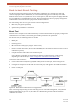


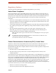


Table Of Contents
- EX-i Series GigE (FDD)
- Digital Microwave Radios
- Installation and Management Guide
- Legal Notice
- Open-Source License Information
- Table of Contents
- List of Figures
- List of Tables
- About this Document
- Introduction
- Pre-installation Tasks
- System Installation and Initiation Process
- Installation
- Configuration and Management
- Command Line Interface (CLI)
- Telnet into the Command Line Interface (CLI)
- Exalt Graphical User Interface (GUI)
- Quick Start
- Navigating the GUI
- Radio Information Page
- Administration Settings Page
- NTP and Time Zone Configurations
- Simple Network Management Protocol (SNMP) Configuration
- File Transfer Page
- File Activation Page
- System Configuration Page
- Allocation Page
- Ethernet Interface Configuration Page
- T1/E1 Configuration Pages
- MHS Configuration Page
- VLAN Configuration Page
- Ethernet Rate Limiting Page
- Ethernet Learning Page
- Syslog Configuration Page
- Ethernet Aggregation
- Cross Connect (X Connect) Page
- Alarms Page
- MHS Status Page
- Performance Page
- ATPC Statistics Page
- Event Log Page
- User Throughput Page
- Diagnostic Charts Page
- Ethernet Utilization Page
- PA Control Page
- Spectrum Analyzer
- Reboot Page
- Manual Page
- Specifications
- Interface Connections
- Troubleshooting
- Back-to-back Bench Testing
- General Compliance and Safety
- Safety Notices
- Regulatory Notices
- Regulatory Compliance
- EIRP Limits for the United States and Canada
- Licensing 6 and 11GHz Models
- Antennas 5GHz Models
- Copyright Notices
- END USER AGREEMENT
- Index

Exalt Installation and Management Guide
EX-i Series GigE (FDD) Digital Microwave Radios
104 202675-008
2016-06-01
Back-to-back Bench Testing
Use back-to-back bench testing to test the radio before installation, pre-configure the radio and
connected equipment before installation, or in the troubleshooting process to identify if the radio
hardware is the source of a system issue. It is a critical process, and often required or highly desirable
for any installation or troubleshooting exercise. This section describes how to properly configure the
radio hardware and accessories for a proper back-to-back bench test.
For radio testing, there are two types of back-to-back configurations:
1 Basic test (test general operation)
2 Specification performance verification
Basic Test
The basic test is a simple test of radio functionality. It verifies that the radios are properly configured to
communicate to one another, and verifies general radio performance as operational.
For the basic test, the following items are needed:
• Radio pair
• Powering source
• RF interconnect cable(s) (any length – short is best)
• Fixed or variable attenuation, between 60 and 90dB (note: attenuation for basic test does not to be
calibrated or precise)
• Computer/terminal with either serial or Ethernet port
If no computer is available, use the temporary hardware configuration key or DIP switch,
depending on radio model (see
Initial Configuration and Back-to-Back Bench Test)
Connect the items as follows:
1 Connect attenuation and (known-good) RF cable(s) between radio pair, shown in Figure 66.
2 Configure the frequencies of the radio to be the same pair, with opposite Tx and Rx orientation.
3 Power on radio pair
Figure 66 Basic back-to-back bench test configuration
After connecting and powering on and connecting a PC for GUI radio management, verify that the
LINK and STATUS are green. If so, the radios are communicating and all radio-related alarm
conditions are normal.